Operation
4-37
1. The 66203/66204 Digital Power Meter has 3 types of parameters
that require TRIG/ENTER for triggering, they are E (Energy), Is
(Inrush Current) and GO/NG. The priority is E > Is > GO/NG.
2. The Integration (INTEG) and Energy (E) calculation are two
separate functions that can be performed at the same time.
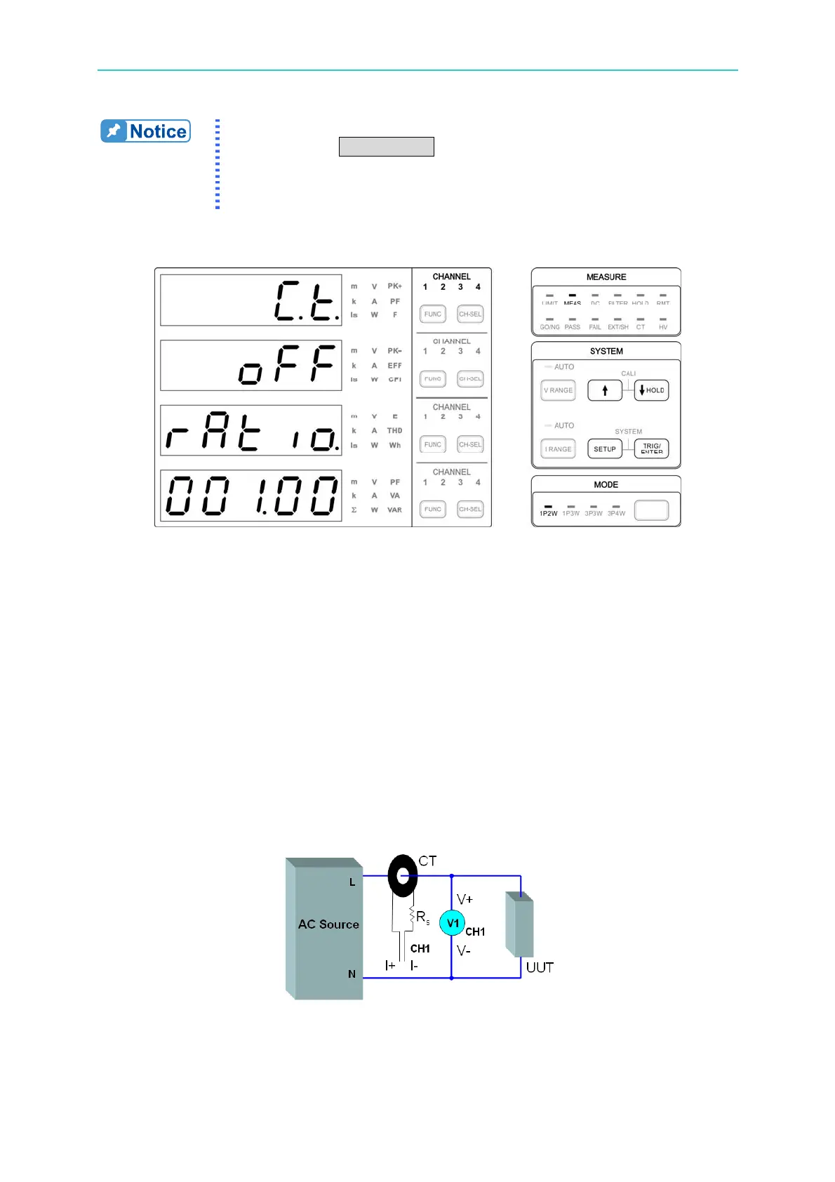
CT
Figure 4-56 CT Setup Screen
If the UUT’s maximum current exceeds the maximum range of the 66203/66204 Digital
Power Meter, the Current Transducer (CT) can be selected to work with the power meter.
The power meter’s CT function needs to be activated and set the conversion ratio. For
instance: if the CT conversion ratio is labeled 1000, the RATIO should set to 1000 and the
limit is 1.00~9999.9.
If it is current output for the CT secondary side, after the R
s
is connected in series, connect
the current input terminal (I+, I-). The current of secondary side goes through the internal
shunt of the power meter and the voltage signal sensed from the 2 ends of shunt will be
transformed into the actual measured current of CT primary side by the power meter. The
CT load resistance of secondary side includes the shunt value inside the power meter and
the R
s
connected externally. Thus, please make sure the total load resistance of secondary
side is within the specification of CT.
The figure below shows the wiring:
Figure 4-57 CT Wiring for I+ & I-
If the CT secondary side is connecting to the load resistance R
s
, when the secondary side
current goes through R
s
, it will convert to sense voltage signal. The voltage signal


 To Next Page