EasyManua.ls Logo

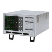
Chroma 66203 User Manual

Chroma 66203
146 pages
To Next Page IconTo Next Page
Page #1 background imageLoading...
Page #1 background image
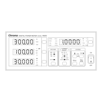
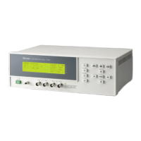
Digital Power Meter
66203/66204
User’s Manual

Table of Contents

Questions and Answers:

Chroma 66203 Specifications

General IconGeneral
Model66203
CategoryMeasuring Instruments
Channels3
Harmonic MeasurementUp to 50th order
DisplayLCD
Current Accuracy±(0.1% reading + 0.1% range)
InterfaceGPIB

Summary

1. Overview

1.1 Introduction

Introduces the 66203/66204 Digital Power Meters and their capabilities.

1.2 Initial Inspection

Provides instructions for inspecting the instrument after unpacking to check for transit damage.

2. Specification

2.1 Standard Specification

Details the electrical and performance specifications for the power meter models.

2.2 Common Specification

Lists general specifications such as display, power, interface, and dimensions.

3. Panel Description

3.1 Front Panel

Describes the controls, indicators, and display elements on the front of the instrument.

3.2 Rear Panel

Identifies and describes the connectors and ports located on the rear of the instrument.

4. Operation

4.1 Preparation for Test

Outlines the necessary steps before performing tests with the power meter.

4.2 System Setup

Covers configuring settings like firmware version, GPIB address, display, and sound.

4.3 Connecting Test Device

Explains how to connect the power meter to the device under test for measurements.

4.4 Computing Equation for Measurement Parameters

Explains the mathematical formulas used for various measurement parameters.

4.5 Setting Measurement Range

Details how to select and configure voltage, current, and external measurement ranges.

4.6 Setting Measurement Functions

Covers setting up measurement functions like Limit, Meas, DC, and others.

4.7 Wiring Mode

Describes the four wiring configurations for single and three-phase power measurements.

4.8 Fans Inspection

Describes the cooling fans and potential error indications.

5. Using Remote Control

5.1 Overview

Introduces the GPIB and USB remote control interfaces for the power meter.

5.2 USB in Remote Control

Details the hardware, protocol, and driver installation for USB remote control.

5.3 The GPIB Capability of the Power Meter

Explains the capabilities and interface functions of the GPIB connection.

5.4 Introduction to Programming

Provides an introduction to programming the power meter via SCPI commands.

5.5 Basic Definition

Defines fundamental concepts and formats used in programming and data transfer.

5.6 Traversal of the Command Tree

Explains how to navigate and use commands within the instrument's command tree structure.

5.7 The Commands of the Power Meter

Lists and describes standard and instrument-specific commands for controlling the meter.

6. Status Reporting

6.1 Introduction

Introduces the status data structure and standard GPIB registers.

6.2 Register Information in Common

Explains common registers like Condition, Event, and Enable registers.

Appendix A Using Control Signal Input/Output Terminal

Limit_Trigger and Is_Trigger

Describes the internal wiring and functionality of limit and inrush current triggers.

Wiring for Pass + / Pass –

Explains the wiring for the Pass/Fail output terminals, indicating test results.

Wiring for Fail + / Fail –

Details the wiring for the Fail output terminals, indicating test failures.

Appendix B Circuit Diagram

Figure B-1 Circuit Diagram

Provides a block diagram illustrating the internal circuitry and signal flow of the power meter.

Appendix C Mapping Table for Displayed Letters

Numbers

Shows the 7-segment display mapping for numerical digits 0-9.

Alphabets

Shows the 7-segment display mapping for alphabetic characters A-Z.

Appendix D Troubleshooting

Error Message Code

Lists and explains the error messages displayed by the power meter and their meanings.

Simple Troubleshooting

Provides basic troubleshooting steps for common issues like power, data errors, and remote control.

Appendix E Specification Verification

Voltage Specification Verification

Outlines the procedure to verify the voltage measurement accuracy across different ranges.

Current Specification Verification

Details the procedure for verifying the current measurement accuracy across various ranges.

Frequency Specification Verification

Describes the steps to verify the frequency measurement accuracy.

Power Specification Verification

Explains the procedure for verifying active power and power factor measurements.

Appendix F A662012 HV Measurement Kit

Safety Precautions

Lists important safety warnings and usage guidelines for the HV Measurement Kit.

Related product manuals