Digital Power Meter 66203/66204 User’s Manual
4-4
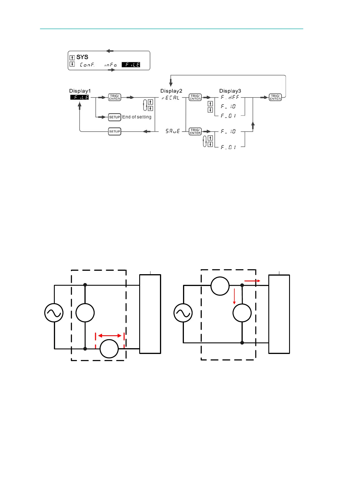
Figure 4-6 Process for Saving & Recalling Setting File
4.3 Connecting Test Device
4.3.1 Standard Connection
The connection of every channel on the single phase or multi-phase (3-phase) of power
meter can select the following two ways. The measurement theory is shown in Figure 4-7
as the diagr
am (a) and (b) shows.
AC
V
AC
UUT
Unit Under
Test
Power Meter
I
AC
V_drop
AC
I
AC
UUT
Unit Under
Test
Power Meter
A_leakage
V
AC
(a) (b)
Figure 4-7 Measurement Theory for Power Meter Connection
The connection of Figure 4-7 (a) is more accurate for current measurement; however, there
is a slight er
ror caused by the measured voltage value plus the voltage drop on the current
meter. It is applicable for middle or small power UUT.
The connection of Figure 4-7 (b) is more accurate for voltage measurement; however, the
measured current will a
dd the leakage current on the voltage meter. It is applicable for
middle or larger power UUT.