Appendix B Circuit Diagram
B-1
Appendix B Circuit Diagram
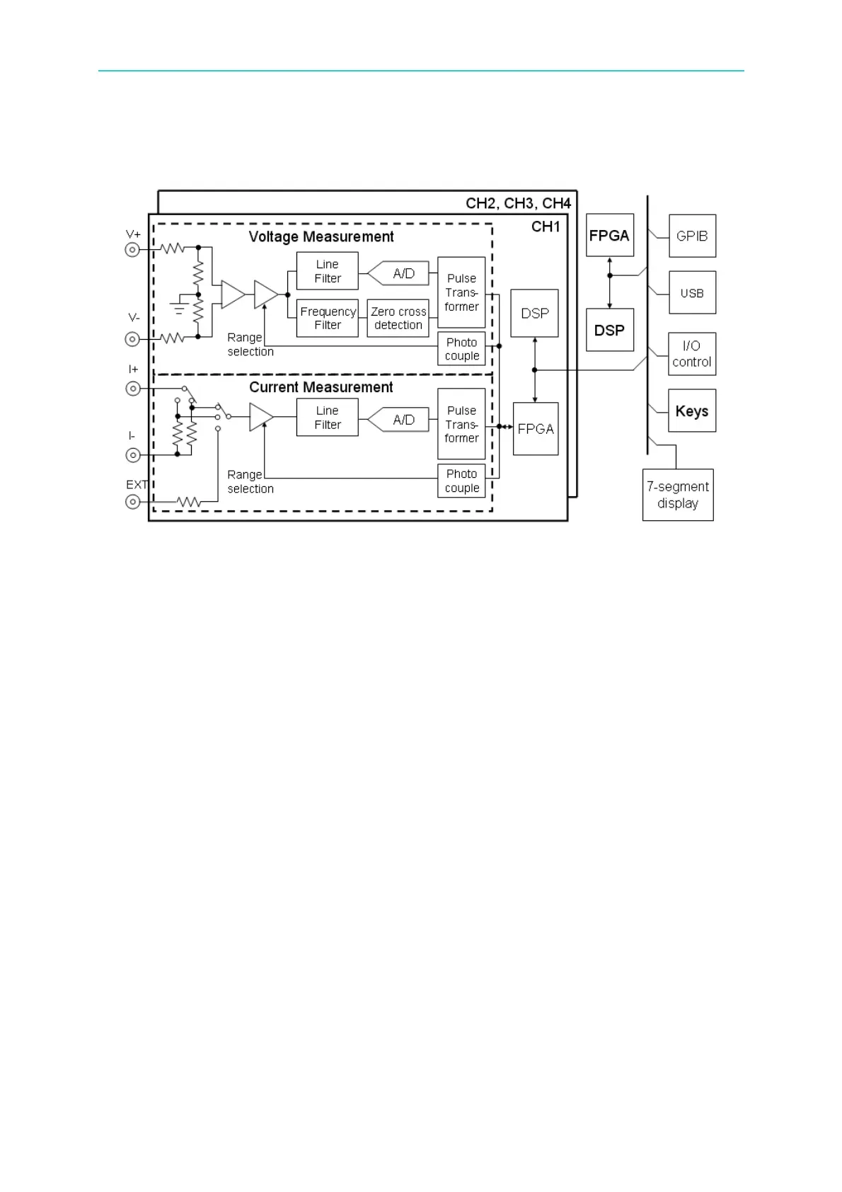
Figure B-1 Circuit Diagram
The 66203 and 66204 Digital Power Meter has 3 and 4 measurement channels respectively.
Each channel has three types of input for measurements which are voltage, current and
external sensing. The external sensing input signal is the voltage signal when the current
flows passing through the sensor for current measurement. Thus, either current or external
sensing input can be used at the same time and share the input low terminal (I-). If current
input is selected for measurement, the power meter will provide two kinds of shunts - low and
high for smaller and larger current measurements. The sensing voltage signal on the shunt
will be processed by amplifier and filter, and then get the sample analog signal via A/D
converter. The sampled data will send to FPGA for simple calculation and then send to
DSP for advance calculation as well as analysis. During the measurement the DSP will
adjust the range to the most appropriate based on the measured current signal to get the
best measurement accuracy. If the current is more than the power meter can afford
(maximum current 20A), an external sensor can be used instead.
Similarly, after the voltage input terminal is inputted with the voltage signal, the signal will be
attenuated and sensed. After the sensing signal is processed by amplifier and filter, the A/D
converter will get the sampling data and send to FPGA for simple calculation and then send
to DSP for further calculation and analysis.
The A/D converter gets the samples of voltage and current signals simultaneously. The
sampling rate is got based on the conversion of voltage frequency and varied with frequency.
The voltage frequency is got using the zero-crossover detection circuit to output signal to
FPGA for calculation. At the same time, the voltage and current data is got by the DSP and
calculation and analysis are performed on current, power and harmonic.
Each measurement channel has its own calculation core, DSP and FPGA. Therefore,
sampling of every channel can be almost at the same time for independent calculation and
analysis. The integrated multi-channel DSP is responsible for the task of outside
communication, user interface and 3-phase power calculation.