Chromalox 2104 Technical Manual 7
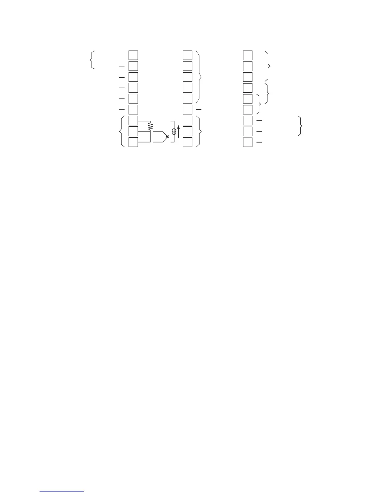
Figure 2.4 Wiring Terminal Identification
Sensor Input Wiring
Sensor Input Wiring Notes:
•Sensor leads (thermocouple and RTD) should not
be run together in the same conduit as power
wiring.
•Twisted pair, shielded wire is recommended for
sensor connections.
•False process readings can occur if the sensor wire
is exposed to electrical noise.
•Ungrounded thermocouples are recommended.
•If thermocouple extension wire is required, it must
be the same type as the thermocouple (i.e., if a
Type K thermocouple is used, then Type K
extension wire must be used).
•Thermocouple wires should connect directly to
the controller terminals. Do not use copper crimp
terminals or solder terminals to make connections.
•If shielded thermocouple wire is used, the shield
must be grounded at one end only, preferably at
the shield ground terminal on the controller, as
shown in Figure 2.5.
•Three wire RTDs are recommended for greatest
accuracy.
•Standard shielded copper wire is recommended for
RTD extensions.
Digital
Input
+24 Vdc Output
Analog Output
Remote Setpoint Input
Common
Sensor Input
RTD TC
1
2
3
4
5
6
7
8
9
10
11
12
13
14
15
16
17
18
19
20
21
22
23
24
25
26
27
Digital
Communications
Not Used
Output #5
Common
Output #4 Relay
100/240 Vac or
12/24 Vac/Vdc
AC Common
Shield Ground
Output #1
and #2
Output #3 Relay
Instrument
Power
4-20mA

 Loading...
