CHRONTEL AN-B014
206-1000-014 Rev. 1.7 2020-07-14 7
• GLED, OLED
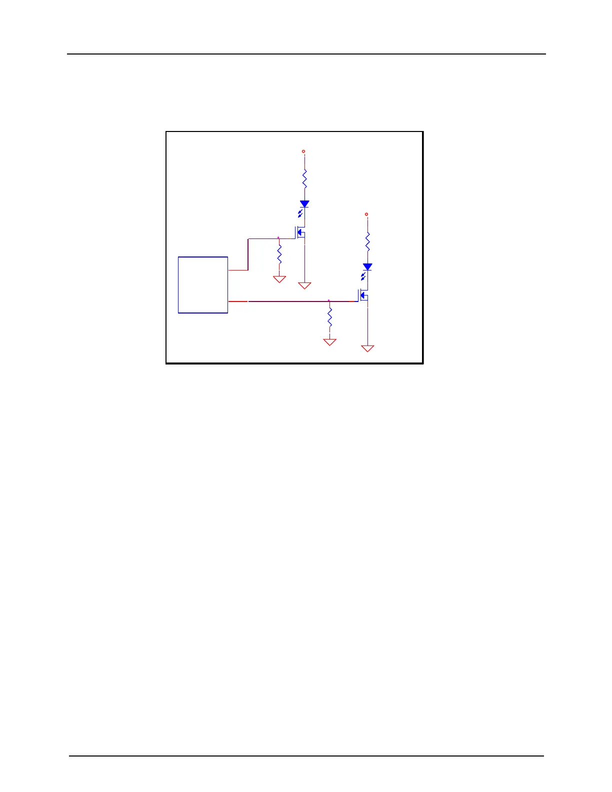
GLED and OLED pins output LED control signals to determine if the CH7511B/7512B is in normal or abnormal
power and mode status. If GLED has output (3.3V), the CH7511B/7512B is in normal status. If OLED has output
(flickers from 0 or 3.3V), the CH7511B/7512B is in abnormal status. The design is shown in Figure 7.
GLED
57
OLED
58
CH7511
GLED
D2
P504CT-ND
R4
100
1
32
Q2
BSS138CT-ND
D1
P504CT-ND
R2
100
+3.3V
+3.3V
1
32
Q1
BSS138CT-ND
R3
10k
GLEDGLEDGLEDGLEDGLEDGLEDGLEDGLEDGLEDGLEDGLEDGLED
OLEDOLED
R1
10k
Figure 7: LED Control
• BLUP, BLDN
1. BLUP is the increase backlight brightness input pin.
2. BLDN is the decrease backlight brightness input pin.
Buttons can be placed at these pins to adjust the backlight brightness. The design is shown in Figure 8.
• PWRDN
The CH7511B/7512B enters into or exits power down state when receiving an active low pulse from this pin. The
connection is shown in Figure 8.