Maintenance Manual 37
PEFS F3 Maintenance Manual, Version 1.2, Feb 2018
© Copyright 2017 Chubb Fire & Security Pty Ltd
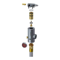
1/8” BSPT x 7/16” JIC (f)swv
¼” NPT x 7/16” JIC (f)swv
¼” Hose with hose protector
Grommet to hold LOP tubing.
Use with P-Clip 103198.
M8 Weld Lug c/w bolt and washer for
mounting P-Clips
Table 16 – PEFS F3 pneumatic actuation hose and tube fittings
Monitoring Components
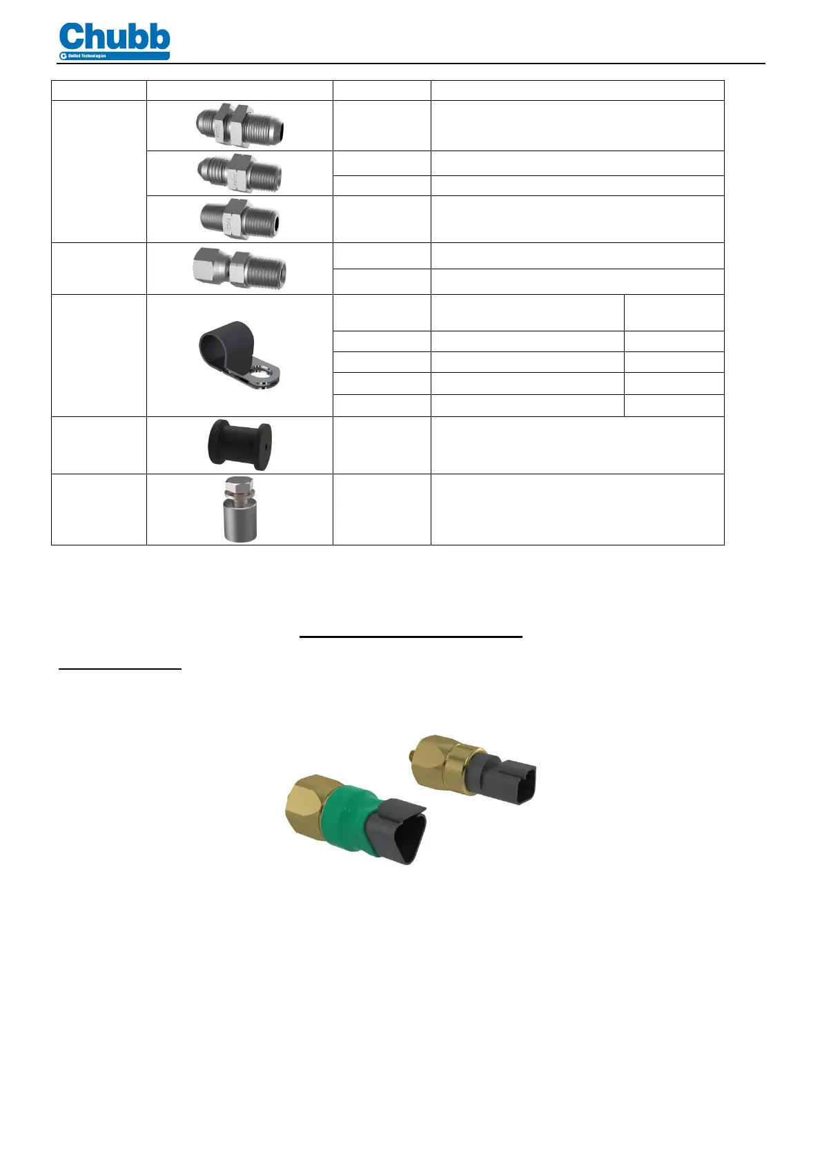
Pressure Switches
“Cylinder low pressure”, 1550kPa NO setting DT04-3P (part number 137060)
“Fire Alarm/Discharge”, 200kPa NC setting DT04-2P (part number 87041)
Figure 19 – Pressure Switches
 Loading...