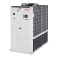
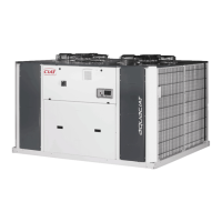
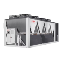
Do you have a question about the CIAT AQUACIAT 2 LD Series and is the answer not in the manual?
Verifies unit model and checks for damage upon delivery, reporting any issues promptly.
Outlines the guarantee period based on the date of first use and invoice date.
Highlights essential safety measures for installation and operation personnel.
Microprocessor-based module controls operations, diagnostics, and compressor management.
Details temperature regulation, fault diagnosis, and operational parameter control.
LP sensor monitors pressure, preventing operation below a set threshold.
HP pressostats and sensors monitor high pressure for safety and regulation.
Sensors protect the evaporator from freezing by controlling compressor operation.
Monitor sensors to prevent exchanger damage by detecting divergent values.
Monitors water flow, cutting compressor power if insufficient.
Protects compressors against overheating and excessive outlet temperatures.
Monitors outlet temperature, cutting compressor power if it exceeds limits.
Units include a mechanism to protect against overpressure due to fire.
Kit monitors phase rotation, absence, and voltage variations for safety.
Essential checks before initial machine startup and installation.
Key checks for correct compressor rotation, temperature, and current.
Adjusting valve to achieve desired nominal flow based on pressure loss.
Verifies correct refrigerant charge by checking sight glass and sub-cooling.
Steps to optimize operation when the unit's mode is inverted.
Guidelines for safe operations, including electrical safety and handling hot/cold surfaces.
Advises using ear protection in high noise environments.
Precautions for handling lubricating oils used in the machines.
Checks to be performed monthly as per operation statement.
Comprehensive checks including oil contamination test and dryer filter.
Connecting the unit's general fault signal to the terminal block.
Connecting a signal for full capacity unit operation to CPU card terminals.
Connects unit's terminal block contacts for unit operation authorization.
Controls cooling or heating mode via a contact on the CPU card.
Connects pump power supply between main board terminals.
Connects contacts to CPU card for load shedding based on compressor count.
Selects setpoint 1 or 2 via a contact on the CPU card.
