- “I” models without plenum or return air sleeves (T5 and T6 only) (Fig.15)
- Mark the three G3 filter clips (a)
- Release the filter from the clips
- Models with plenum or return air sleeves (T5 and T6 only ) (Fig.16)
- Press the two filter access bolts (a)
- Support the access panel as it is lowered and release the filter from its housing (b)
5.2 Condensate drain pan
The main condensate drain pan and the pan extension must be kept clean. The pans
and drainage fittings may be completely cleaned using non-abrasive, water-based
detergents. Also check periodically that the drain pipe is not blocked, bent or kinked,
and has the required gradient of -0°/+2° along its entire length.
Before starting up the unit, check that the water flows properly into the condensate
pan by pouring some water into it.
• Removing the pan:
Firstly, disconnect the pump (if present) and the condensate drain.
- Refer to the "Removal of the coil" section to remove the pan.
Note: Before starting up the unit, check that the water flows properly into the
condensate pan by pouring some water into it. If the flow is not correct, look
for possible causes of the problem.
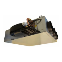
5.3 Fan motor assembly
Periodically check the cleanliness of the impeller and the motor. If necessary, clean
them using a vacuum cleaner, taking care not to damage them.
The electric motor's bearings are lubricated for life and do not require specific
maintenance.
• Removing the fan motor assembly (GMV):
WARNING: Disconnect the power supply to the unit before carrying
out any work on the unit.
- Suspended ceiling (Fig. 13) :
- Remove the removable lower panel (a) using the 4 screws.
- Ensure the filter is supported as it is lowered as the only support is provided by
the removable panel.
- Disconnect the electrics for the FMA (refer to the note below according to the type
of motor in the unit).
- If one or more electrical heaters are fitted, these must be disconnected from the
control panel, then the lower coil access panel must be removed using the 4
screws.
- Undo and remove the 4 FMA retaining screws on the lateral panels (b).
- Support the FMA platform as it is lowered, following the recesses (not present on
T5 and T6) provided in the lateral panels (c).
- Perform the steps in reverse to reassemble, taking care to ensure the insulation
is not damaged.
EN-31 COMFORT LINE™
 Loading...