11
Toutes les poulies moteurs et ventilateurs sont à double gor-
ges. Après avoir déterminé la pression disponible désirée en
fonction des combinaisons poulies moteur/ventilateur suivre
la procédure suivante :
– Exemple 1 LJ 100 : en standard usine on a :
– Pression disponible : 15 mmCE
– Poulie moteur : ø 95 mm
– Poulie ventilateur : ø 180 mm
– Vitesse de rotation : 728 tr/mn
Pour une pression disponible de 20 mmCE (tableau LJ 100), il
faut une transmission ayant les caractéristiques suivantes :
– Pression disponible : 20 mmCE
– Poulie moteur : ø 90 mm
– Poulie ventilateur : ø 160 mm
– Vitesse de rotation : 776 tr/mn
– Procédure
All motor and fan pulleys have a double groove. After deter-
mining the desired available pressure as a function of the fan/
motor pulley combinations, proceed as follows :
–
Example 1 LJ 100 : factory standard version :
– Available pressure : 15 mmWG
– Motor pulley : ø 95 mm
– Fan pulley : ø 180 mm
– Rotation speed : 728 rpm
For an available pressure of 20 mmWG (table LJ100), a trans-
mission drive with the following characteristics is required:
– Available pressure : 20 mmWG
– Motor pulley : ø 90 mm
– Fan pulley : ø 160 mm
– Rotation speed : 776 rpm
–
Procedure
1 4 2 3
5
6
7
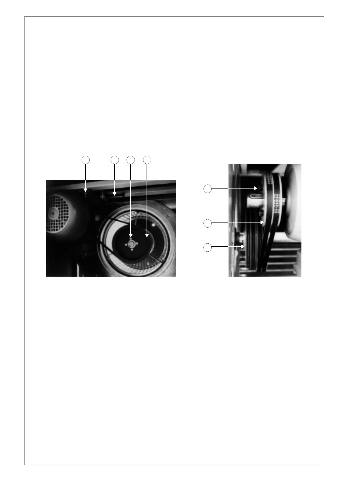
A) Démontage des courroies
1°) Desserrer les 4 boulons fixant le moteur (rep. 1).
2°) Faire coulisser le moteur afin de détendre les courroies
(dévisser le boulon rep. 4).
3°) Enlever les courroies hors de la gorge des poulies.
B) Démontage de la poulie du ventilateur
1°) Dévisser complètement les 4 vis (rep. 2)
2°) Enlever la poulie ventilateur : ø 180 mm (rep. 3)
3°) Monter la 2ème poulie ventilateur : ø 160 mm située à côté
de la 1ère poulie (rep. 7).
4°) Fixer la poulie ventilateur avec les 4 vis.
C) Démontage de la poulie du moteur
1°) Dévisser complètement les 2 vis (rep. 5)
2°) Enlever la poulie moteur : ø 95 mm (rep. 6)
3°) Monter la 2ème poulie moteur : ø 90 mm située dans l’ar-
moire électrique.
D) Remontage des courroies
1°) Remonter les courroies
2°) Tendre la transmission en agissant sur le boulon (rep. 4)
3°) Serrer les 4 boulons fixant le moteur (rep. 1)
A) Dismounting the belts
1
°
) Loosen the 4 bolts fixing the motor (ref 1)
2
°
) Slide the motor to slacken the belts (unscrew the bolt
ref 4)
3
°
) Lift the belts out of the pulley grooves
B) Dismounting the fan pulley
1
°
) Completely loosen the 4 screws (ref 2)
2
°
) Remove the fan pulley : ø 180 mm (ref 3)
3
°
) Mount the second fan pulley ø 160 mm located beside the
first pulley (ref 7)
4
°
) fix the fan pulley with the 4 screws
C) Dismounting the motor pulley
1
°
) Completely loosen the 2 screws (ref 5)
2
°
) Remove the motor pulley ø 95 mm (ref 6)
3
°
) Mount the 2nd motor pulley ø 90 mm located in the electri-
cal panel.
D) Remount the belts
1
°
) Remount the belts
2
°
) Tension the belts by turning the bolt (ref 4)
3
°
) Tighten the 4 bolts fixing the motor (ref 1)
 Loading...