Do you have a question about the CIAT V200 and is the answer not in the manual?
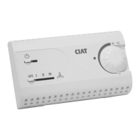
Details how to adjust the comfort mode temperature using the control dial (1) for heating and cooling setpoints.
Explains how to select between auto and manual fan speed modes, including auto speed operation based on temperature.
Explains how a master unit controls up to 15 slave units, communication, and distance limits.
Details the economy input function, activated by a closed contact for reduced settings.
Describes the window contact input for switching to anti-freeze mode based on window status.
Details the function of eight switches (D1-D8) for configuring the controller's behavior and settings.
Explains how switches D5 and D6 adjust the width of the neutral zone for ventilation.
Explains the meaning of red, green, and yellow LEDs indicating thermal function status.
Explains the meaning of the yellow LED for communication status and controller conditions.
Explains yellow LED flashing patterns (10% and 50%) indicating communication status and alarms.
Describes how to use the D8 switch to test the controller's analogical inputs.
Explains PI control parameters (proportional band, integration time) and how to select slow or fast settings.
Details centralized management for independent offices, where users can modify setpoints and control functions.
Describes single-zone centralized control for areas like open spaces, managed by a pilot controller.
Illustrates a technical plant setup with a control cabinet, heliothermes, and sensors for zone management.
Provides attention points for wall thermostat installation, mounting, and wiring, emphasizing safety and compliance.
Details the wiring and function of economy input and window contact input for system control.
Explains how to operate terminals for different system types like 4-pipe, 2-pipe heating/cooling, etc.
| Brand | CIAT |
|---|---|
| Model | V200 |
| Category | Controller |
| Language | English |