10
Centralized unit-heater management
The example given below shows how a works-
hop area, storage area or DIY store can be
managed with up to 50 heliothermes providing
heat or cool air.
Zentralisierte Verwaltung für Lufterhitzer
Das Beispiel unten zeigt die Verwaltung einer
Werkstätte, eines Lagers oder eines Bastel-
Supermarkts… mit bis zu 50 Héliothermen, die
heizen und kühlen.
Gestion centralisée pour Aérothermes
L'exemple ci-dessous présente la gestion d'une
zone d'un atelier, d'une zone de stockage ou
d'une Grande Surface de Bricolage (GSB),…
comprenant jusqu'à 50 héliothermes fonction-
nant en chauffage et rafraîchissement.
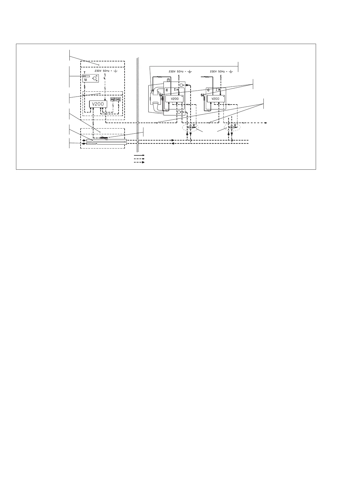
A controller in the machine room manages
the area centrally. Each heliotherme includes
an inherent controller and a cutout switch with
both padlock protection and fuse protection
incorporated in an enclosed electrical cabi-
net, waterproof (IP55),and own return air
temperature sensor.
A change-over sensor is fitted which detects
when the operating mode (heating or cooling
supply) is changed.
A 3-way valve can be supplied for water
control.
This regulator transmits all the information
needed by the heliothermes to operate: the
set point temperature defined by the site
manager, operating modes (comfort, economy,
anti-freeze), water temperature (heating or
cooling mode).
1 or 2 H1 and H2 clocks can be fitted to the
controller so that the economy and anti-free-
ze modes can be programmed to operate at
set times.
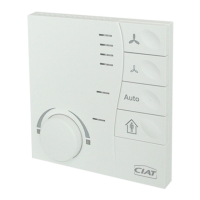
Installing the wall thermostat
Attention !
This device must be installed according to the
wiring diagram on the inside of the housing. It
must be installed according to industry stan-
dards and in compliance with applicable local
electrical codes. To meet Class II require-
ments, it is essential that the corresponding
installation rules be followed.
Mounting: directly on wall using the moun-
ting slots. Feed wires through pre-cut holes in
wallplate.
Electrical wiring:
- Remove the front panel from the terminal
- Connect as shown in the housing
Electrical connections
Supply
- 230 / 1 / 50 or 230 / 1 / 60
Control Box / Controller connection
– Maximal distance between the control box
and the controller : 30 meters.
– Wiring : 3 or 4 shrouded and twisted wires
with the shroud linked to the fan-coil earth.
Ein Regler zentralisiert in einem Betriebsraum
die Kontrolle des Bereichs. Jedes Héliotherm hat
seinen eigenen Regler und abschliessbaren
Hauptschalter mit Sicherung in einem geschlos-
senen, IP55 dichten Elektrikgehäuse sowie sei-
nen eigenen Rückluft-Temperaturfühler.
Ein change-over Fühler ist angeschlossen, um
eine Funktionsmodus-Änderung festzustellen
(Heizen oder Kühlen).
Bei einer Wasser-Regelung kann ein 3-Wege-
Ventil geliefert werden.
Alle erforderlichen Informationen zum Funktionieren
der Héliotherme/Sonnenklimageräte des Raums wer-
den durch diesen Regler übermittelt: vom
Raumbetreiber festgelegte Sollwert-Temperatur,
Funktionsarten (Komfort, Ersparnis oder Frostfrei),
Wasser-Temperatur (Heiz- oder Kühlmodus).
1 oder 2 Uhren H1 und H2 können an den
Steuerregler montiert werden, welche eine
Stundenprogrammierung der Funktionsarten
Ersparnis / Frostfrei ermöglichen.
Anbringung des Wandmodells
Achtung!
Dieses Thermostat ist gemäß dem Schaltplan im
Gehäuse zu verdrahten. Die Installation hat
fachgerecht und gemäß den geltenden
Landesvorschriften und Gesetzen zu erfolgen.
Zum Erhalt eines Systems der Klasse II sind die
entsprechenden Installationsvorschriften
einzuhalten.
Befestigung: direkt an der Wand über die hierfür
vorgesehenen Bohrungen. Kabeldurchführung
durch die gestanzten Aussparungen im Sockel.
Stromverkabelung:
- Die Vorderfront des Bediengeräts entfernen
- Gemäss Gehäuseschema anschließen
Elektrische Anschlübe
Einspeisung
- 230 / 1 / 50 oder 230 / 1 / 60
Verbindung Bediengerät/Regler
– max. Abstand zwischen Bediengerät und
Regler : 30 m
– Kabel : 3 Adern oder 4 Adern verdrillt und
abgeschirmt, die Schirmung muß mit der Erde
des Klimakonvektors verbunden sein.
Un régulateur, en local technique, centralise
le contrôle de la zone. Chaque héliotherme
comporte son propre régulateur et un inter-
rupteur sectionneur général cadenassable
avec protection par fusible intégrée dans un
coffret électrique fermé, étanche IP55 ainsi
que sa propre sonde de température à la
reprise.
Une sonde change-over est raccordée afin
de détecter le changement du mode de fonc-
tionnement (chauffage ou rafraîchissement).
Une vanne 3 voies pourra être fournie dans le
cas d'une régulation sur l'eau.
Toutes les informations nécessaires au fonc-
tionnement des héliothermes du local sont
transmises par ce régulateur : température de
consigne fixé par l'exploitant du local, régi-
mes de fonctionnement (confort, économie
ou hors-gel), température de l'eau (mode
chauffage ou rafraîchissement).
1 ou 2 horloges H1 et H2 peuvent être mon-
tées sur le régulateur de contrôle permettant
une programmation horaire des modes éco-
nomie et hors gel.
Installation version murale
Attention !
Cet appareil doit être installé selon le schéma
de branchement situé à l'intérieur du boîtier. Il
doit être installé selon les règles de l'art et en
conformité avec les normes locales en
vigueur. Pour répondre à la classe II, il est
indispensable d'observer les règles d'installa-
tion correspondantes.
Fixation : directement sur le mur par les
trous prévus à cet effet. Passage de câbles
par l'ouverture présente dans le socle.
Câblage électrique :
- Oter la face avant du terminal
- Brancher selon le schéma du boîtier
Raccordements électriques
Alimentation
- 230 / 1 / 50 ou 230 / 1 / 60
Liaison terminal / régulateur
- distance maxi entre terminal et
régulateur : 30 m.
- câblage : 3 fils ou 4 fils torsadés
blindés avec blindage relié à la terre
du ventilo-convecteur.