61
- FIX the support of the remote keyboard on the cold room wall using screws (Fig. 1.3.1.a).
- CONNECT the cable to the relative terminals (Fig. 1.3.1.b).
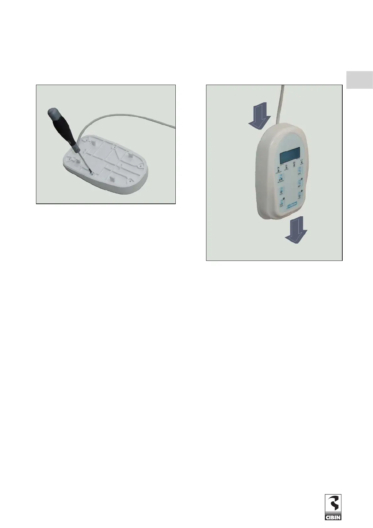
- CLOSE the coverage of the remote keyboard using the provided screws (F
ig. 1.3.1.c).
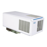
- INSTALL the remote keyboard on the support (Fig.
1.3.1.d).
1.3.2 DOOR SWITCH CONNECTION (pre-set machines only)
Where required, connect the door switch as indicated in the electrical diagram. Some machines are supplied with a cable bridge
on the door switch terminals, this must be removed when a door switch is installed.
Use only shielded cables to connect the door switch (see wiring diagram).
1.4 WATER SUPPLY CONNECTION (pre-set machines only)
When connecting to the water supply, follow t
he inlet (blue) and outlet (red) directions of the water supply.
Connect to the respective couplings on the unit.
Remember that the diameters of the connection pipes must never be less than those of the pipes of the equipment.
The minimum working pressure for good water circulation must never be less than 1 bar or more than 5 bar.
Fig. 1.3.1.c
Fig. 1.3.1.d
GB