06
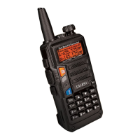
5.- INSTALLATION OF ACCESSORIES:
5.
1.- INSTALLING THE ANTENNA:
Install the antenna as
shown In
the figure below and turn It clockwise until
It stops.
Note:
- When Installing th
e
antenna, don't rotate it by its top,holdlog It by
its base and turn.
-
If you us
e
an external antenna, make sur
e
the 'SWR' is about 1.5:1
or less, to avoid damage to the transceiver's final transistors.
- Do not hold the antenna with your hand or wrap the outside of it
to avoid bad operation of the transceiver.
- Never transmit without an antenna.
5.2.- INSTALLING THE BELT CLIP:
lf necessary, Install the belt clip at th
e
rear of the battery compartment
t
cover as shown in th
e
figure below.
.:.:,;;
-:
-
Note:
- Do not use any kind of glu
e
to fu
th
e
screw on the belt clip. Th
e
solvents Glue may damage the battery casing.
5.3.- MICRO-HEADSET INSTALLATION OF EXTERNAL:
Plug the external micro-headset connector into the jack of 'SP. & MIC'
of th
e
transceiver as shown in the figur
e
below.
S.
4
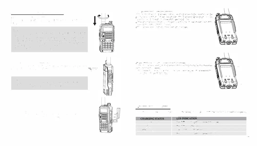
.- BATTERY INSTALLATION:
-When attaching th
e
battery, make sure the
battery
is in
parallel and
in
good contact with the aluminum chassis. The battery bottom Is about I to
2 centimeten below the bottom of the radio's body.
-Align
the battery
with the
guide rails on the aluminum cha.nu
and slide
ii upwards until a
'click'
is beard.
-The
battery latch at the bottom locks the battery.
-Turn
off
the
radio befor
e
removing the battery.
-Slid
e
th
e
battery latch, at the bottom of
the
radio's body,
in the
direction
indicated by th
e
arrow.
-SUd
e
down the battery for about 1 to 2 centimeters, and then remove the
battery from the radio's body.
6.-BATTERY CHARGING:
\
\
I
Us
e
only th
e
charger
sp
e
cifi
e
d by th
e
manufacturer. Th
e
charg
e
r
'
s LED indicates the
charging progress.
Standby (no-load)
Charging
Fully Charged
Error
Red
LED
ftashes,
w
hil
e
Green LED glows
Red LED solidly
glows
Gr
e e
n LED solidly glows
Red
LED
ftash
e
s,
w
hil
e
Green
LED
glows
07