TRANSMIG 350i, 450i, 550i
INSTALLATION, OPERATION AND SETUP
3-12 Manual 0-5205
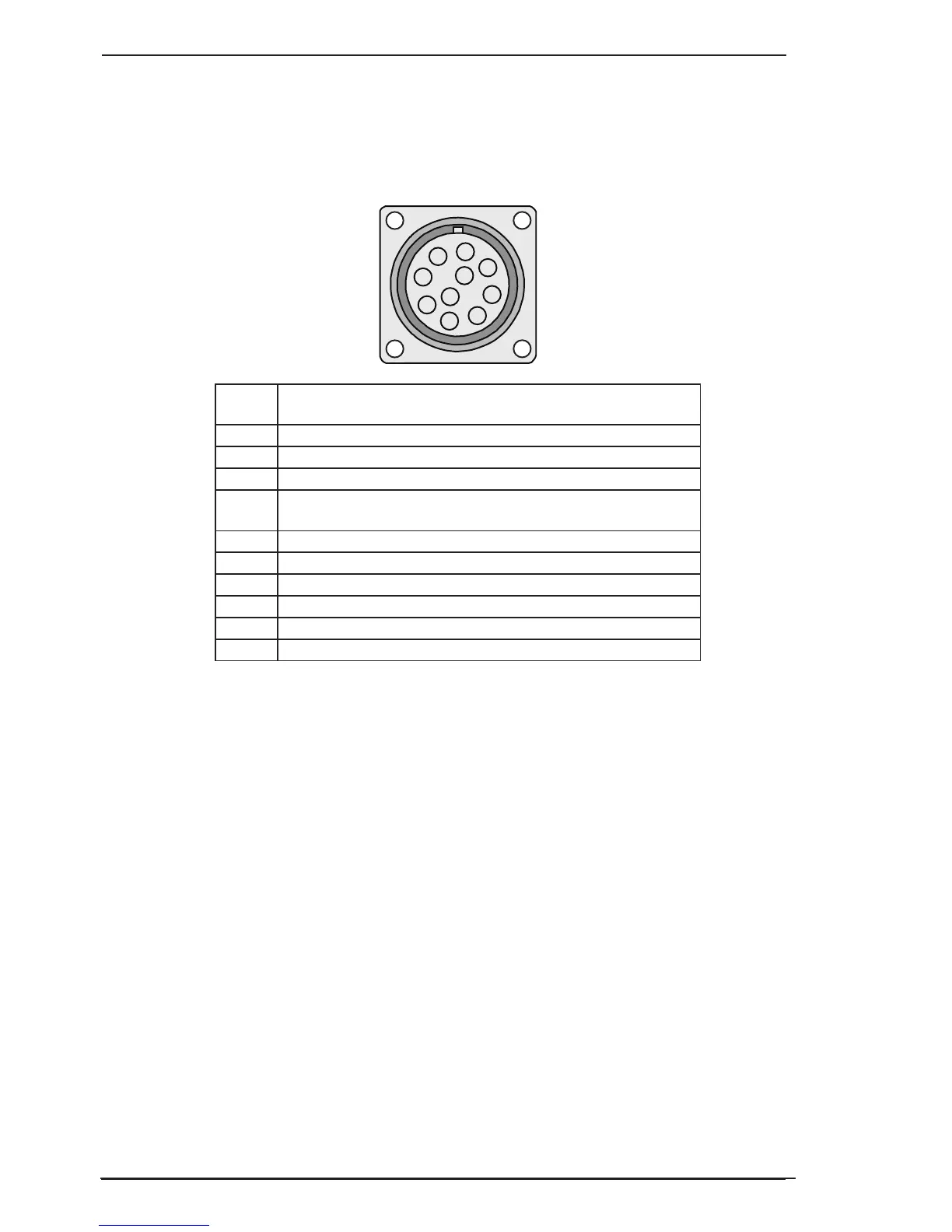
20. 10 Pin Control Socket
The 10 pin receptacle is used to connect a Wirefeeder or other suitable remote control device to the weld-
ing Power Source circuitry:
To make connections, align keyway, insert plug, and rotate threaded collar fully clockwise. The socket
information is included in the event the supplied cable is not suitable and it is necessary to wire a plug or
cable to interface with the 10 pin receptacle
A
B
C
D
E
F
G
H
I
J
A-10636
Socket
Pin
Part Number / Description
A Remote Voltage Control Potentiometer Wiper
B Motor Negative
C Motor Positive
D Contactor + (Contact closure is provided between socket
pins D and G to energise the contactor)
E Remote Voltage & Wirespeed Control Potentiometers Maximum
F Remote Wirespeed Control Potentiometer Wiper
G Contactor Negative, Solenoid Negative
H Remote Voltage & Wirespeed Control Potentiometers Minimum
I Solenoid Positive
J Not used
Table 3-2: 10 Pin Interconnection Control Plug configuration
 Loading...