4 5
ENGLISH
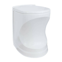
PLACING THE TOILET
The toilet has a Build-in module that must be built into the wall. You can also create a box around the
Build-in module. Clearance between Build-in module and rear wall is recommended, approx. 5mm.
Please note that recommended panel thickness is 8mm, and a thicker panel will reduce the space for
insulation around the exhaust hose. Sucient insulation space must be maintained, in order to main-
tain the insulation properties.
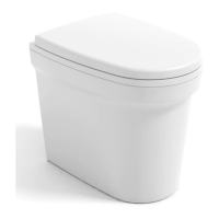
If the oor is molded in a hard plastic material, preventing you from placing the toilet where you would
prefer it, the material may need to be removed, and a new oor installed, unless it is possible to modify
parts of the oor. You should consider that the ash container insert regularly must be emptied. This will
require at least 40 cm space in front of the toilet. There must be at least 5 cm clearance on each side of
the toilet, but keep user comfort in mind and provide extra room if possible.
The toilet has four xing points to the oor. Remove ash container for access. If the bathroom has oor
heating, take precautions when xing the toilet to the oor.
EXHAUST AIR
Exhaust hose with insulation is fed from roof feed-though ange to the toilet and secured at each end
with a powerful hose clamp that is included in the installation kit. Avoid horizontal stretches (max.
60cm) and turns as far as possible as this creates counter pressure and will cause increased stress on
the toilet over time and the possibility of overheating. Bends should be as gentle as possible. Under
no circumstances should negatively fall or sharp 90° bends occur as this will cause overheating of the
product. The insulation must not be squeezed as this aects the insulating and special care must be
taken for proper sealing in both ends. Exhaust hose should be mounted to toilet and feed-through
ange with exhaust paste to avoid leakage.
On top of the roof feed-through ange, a chimney cap is mounted, this is included in the toilet box.
If there are larger objects within one meter of chimney cap, or if there is snow on the roof that can
prevent air ow, an extension must be mounted between the ange and the chimney cap.
The roof feed-through ange must be placed in a at area of the roof, to ensure proper sealing. Find a
suitable place where the ange makes good contact with the roof and make a hole in the roof with an
83mm hole saw. Take precautions when making the hole through the roof, to avoid electric cables.
Be sure to use enough sealant between the ange and roof to ensure no water ingress. Roof feed-
through is in material quality EN 1.4016. Take necessary precautions to avoid galvanic corrosions.
Fasten roof feed-through ange with appropriate stainless steel screws.
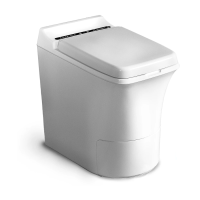
SKETCH OF AN INSTALLATION
Chimney cap
Insulation
Inspection hatch
Inlet air hose
Roof feed-through
Exhaust hose
Build-in Module
Inlet air ange
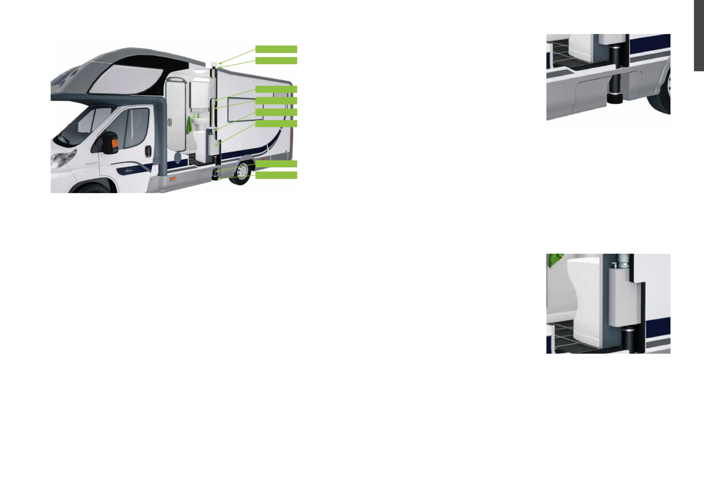
INLET AIR
An inlet air hose is included in the installation box. Use a
83-mm hole saw for implementation in ooring. An op-
tional oor nozzle is available for double oors. Consider
air supply into double oor compartment for sucient
air ow.
If the wheel arch or other obstructions prevent the hose
from going directly down, it can be bypassed, but make
sure the hose is routed with gentle bends and as short a
stretch as possible, maximum hose length 1.2 m. Finish
with oor nozzle under oor exterior. The hose may be
insulated, if desired.
An air grate can be used in both oor and wall, but make sure you have a minimum 50cm² light open-
ing and that you protect against water intrusion. Please note that oor intake is preferred instead of
wall intake. If the toilet in large parts of the year is used in cool climates that experience extreme cold
for extended periods, condensation may form on the outside of the toilet. It may be advantageous to
preheat the air in. This can be done using a radiator connected to the heating system that preheats the air.
GAS INSTALLATION
The gas is supplied through an 8mm pipe directly to the toilet with an angled compression tting on
top of the build-in module. No adjustment of tting is allowed. The toilet is designed to run on LPG. If
you know that you frequent areas with low quality LPG, a lter should be considered. A separate gas
shut-o valve is required when connecting to an existing gas supply line.
This will aid trouble shooting and allow operation of other appliances in case of dismounting the toilet.
The connector is a brass compression coupling which takes ø8 pipe. Be sure to clamp the pipe close to
the tting to avoid stress fatigue in the pipe.
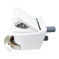
INSPECTION HATCH
There must be access to the top of the Build-in module
for easy access to connections. This allows for annual
inspection and leak testing of the gas connection.
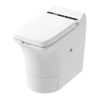
CONTROL PANEL
Locate the desired placement of the control panel.
Create an opening for the signal cable and route the
cable out here. The signal cable is a at cable with ap-
prox. 20mm width.
Connect the signal cable together with the control cable
and fasten the control panel. The signal cable can be
connected in two ways, but only one way is correct.
If you get a red light, and not a green, reconnect signal
cable the opposite way. The signal cable is approx.
150cm long.
CONNECTING AND TEST OF TOILET
Testing procedure after installation and before adding panels and closing hatches
• Open main gas supply valve from gas container
• Check for gas leakages on supply line
• Turn om main switch located inside toilet
• Open and close toilet lid
• Start incineration on control panel
• Wait 2-3 minutes for continuous incineration
• Stop incineration by pressing incineration button until a long beep is heard (approx. 9 sec)
• Close main gas supply valve from gas container
If you do not have the control panel in place yet, you can still test the toilet by connecting the control
panel to the signal cable.
 Loading...