The CircuPool EDGE-Series Saltwater Chlorination System is an advanced swimming pool sanitation device designed to continuously generate free chlorine from a low level of salt in pool water, effectively killing bacteria and algae. This system offers an escape from routine manual pool chlorination and sanitization.
Function Description:
The EDGE-Series operates on the principle of electrolysis. It applies a small electric charge across a set of titanium plates within the Electrolytic Cell. This process converts salt (sodium chloride, NaCl) in the pool water into sodium hypochlorite (NaOCl). Sodium hypochlorite then dissociates into sodium (Na+) and hypochlorite (OCl-) ions. The hypochlorite ions combine with hydrogen (H+) ions from the water to form hypochlorous acid (HOCl), which is the active agent responsible for destroying bacteria and algae and oxidizing organic matter. This form of chlorine works quickly in the pipe, leaving a mild residual in the pool. Additionally, the Electrolytic Cell continuously "shocks" the incoming water, burning off oils, organic matter, and other particles that need to be oxidized. The system continuously recycles the salt, meaning the original molecules reform after cleaning the pool, and the salt itself is not consumed.
The system comprises three main components:
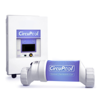
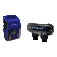
- Control Module: This wall-mounted unit supplies power to the Electrolytic Cell and allows users to customize the system's operation. It features an on/off button, "Adjust" and "Boost" buttons for chlorine output, a chlorine power level display (LED bar), and system message indicator lights (check cell, low salt, system error, water flow).
- Electrolytic Cell ("Cell"): This component, containing bipolar titanium plates, is where chlorine is created as water passes through it. It is installed in the pool's return line.
- Flow/Temperature Sensor: These components ensure adequate salinity and water flow for the Cell to activate and monitor temperature to protect the Cell. The flow switch must be properly oriented to detect water flow.
Important Technical Specifications:
- Ideal Salt Level: 3000-4500 ppm (parts per million), with an ideal level of approximately 3500 ppm.
- Chlorine Output: Adjustable via the Control Module, with a "Boost" mode for maximum output for 24 hours of system run time.
- Water Flow Rate: A minimum water flow rate of 20 gpm is required for safe operation of the electrolytic cell.
- Power Supply: The Control Module uses a switch-mode power supply designed to automatically accept either 120VAC or 220VAC. It has built-in power protection mechanisms.
- Plumbing: Typically designed for 2" plumbing, with reducer bushings available for 1.5" plumbing.
- Installation Distances: The Control Module should not be installed within 10 feet of pool edges. The Flow Switch should be upstream from the cell with at least 6 to 12" (30cm) of straight pipe before it.
Usage Features:
- Manual On/Off: The Control Module allows for manual activation and deactivation of the system.
- Adjustable Chlorine Output: Users can adjust the chlorine production rate to meet their pool's specific needs using the "Adjust" button. The chlorine power level is indicated by an LED bar.
- Boost Mode: A "Boost" button activates super-chlorination mode, providing maximum output for 24 hours to address heavy bather loads or high chlorine demand. The system automatically returns to the previous setting after 24 hours.
- System Diagnostics: LED lights on the Control Module provide important information about system operations, including "check cell," "low salt," "system error," and "water flow" warnings, aiding in troubleshooting.
- Compatibility: Designed for use with both standard and variable speed pumps. When wired parallel to the pump, both turn on and off together. For variable speed pumps, the Control Module can be wired directly to the power source, allowing the flow switch to control cell activation.
- Pool Chemistry Management: The system requires balanced pool water chemistry, with specific ideal ranges for Free Available Chlorine, Salinity, pH, Total Alkalinity, Calcium Hardness, Stabilizer (Cyanuric Acid), Saturation Index (LSI), Phosphates & Nitrates, Metals, and TDS.
Maintenance Features:
- Cell Cleaning Notification: The "CHECK CELL" LED light illuminates when the Electrolytic Cell requires cleaning due to mineral scaling.
- Electrolytic Cell Cleaning Procedure: Detailed instructions are provided for safely cleaning the cell using a diluted muriatic acid solution. This involves temporarily removing the O-ring, attaching a cleaning cap, soaking the cell in the acid solution, and then flushing it with water. Safety precautions, such as wearing protective gear and adding acid to water (never water to acid), are emphasized.
- Mineral Buildup Prevention: Maintaining proper water chemistry, particularly the Saturation Index (LSI) between -0.2 and +0.2, is crucial to prevent excessive calcium scaling on the cell.
- Salt Level Monitoring: The "LOW SALT" LED indicates when salt may need to be added. Users are advised to manually check salinity and add salt according to a provided chart.
- Winterizing: The system automatically reduces chlorine production at low temperatures to extend cell lifespan. Instructions are provided for draining the Electrolytic Cell and plumbing in areas prone to freezing temperatures. The Control Module does not need to be removed during winter.
- Spring Start-up: Before powering on after inactivity, pool water chemistry must be balanced, and salt added if water was drained.
- Cell Replacement: Replacements for the titanium blades inside the Electrolytic Cell are readily available. The "Check Cell" LED will flash when the cell is nearing the end of its lifespan, eventually becoming solid when replacement is recommended.
- Control Module Reprogramming: Instructions are provided for resetting the system's internal production hour count when installing a new cell of the same size or clearing the flashing "Check Cell" LED. Separate instructions are given for reprogramming the Control Module when installing a new cell of a different size (e.g., upgrading to a larger size).
- Troubleshooting Guide: A comprehensive troubleshooting section helps diagnose common issues based on system behavior (e.g., low chlorine residual, no power, specific LED lights illuminated) and provides suggested actions.
- Warranty: A limited warranty covers manufacturing defects for residential use, with a prorated schedule for parts replacement over seven years. Commercial use has a one-year warranty. Exclusions include damage from improper pool chemistry, installation, maintenance, service, or environmental factors.