Código
code
Tipo
Type
Sensibilidad (A)
Sensivity
Retardo disparo (s)
Tripping delay
Comunicaciones
Communications
P11941
RGU - 10
0,03-0,1-0,3-0,5-1-3
por ajuste directo
by direct setting
5-10-30 por/by SETUP
INS-SEL-0,02-0,1-0,2-0,3-0,4-0,5-0,75-1
por ajuste directo / by direct setting
3-5-10 por/by SETUP
No disponible
Not available
P 1 X X X X 0 0 X
Código
Code
Código interno
Internal code
Tensión de
alimentación
Power supply
230 V c.a.
110 V c.a.
0
1
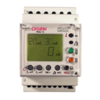
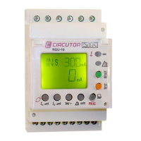
Relé de protección diferencial electrónico RGU-10
RGU-10 Electronic Earth-leakage Protection Relay
Por ejemplo RGU-10 alimentado a 110 V c.a / For instance RGU-10 110 V a.c...supplied by
- Dispositivo con 2 relés programables independientes, canal principal y canal de prealarma.
- Dispone de 2 salidas. Disparo de relé principal y la de señalización por prealarma.
- Dispone de 1 entrada libre de potencial para realizar un Disparo/Rearme exterior.
- Montaje en Carril DIN 46277 (EN 50022) o en panel 72x72 mediante accesorio (M5ZZF1)
- Asociado a transformador de corriente diferencial externo serie WGC
- Comprueba conexión con transformador exterior WGC mediante test inductivo.
- La detección y medida de la fuga se realiza calculando su verdadero valor eficaz (TRMS).
- Visualización por display de los valores de ajuste y de la corriente de fuga instantánea.
P11941001
RGU - 10 C
Pag. 1/4
24/ 48 V c.a/a.c
24/120 V c.c/d.c
4
DESCRIPCIÓN GENERAL
GENERAL DESCRIPTION
CONSIDERACIONES INICIALES
COMPROBACIONES A LA RECEPCIÓN
Asegurarse del cumplimiento de:
- El equipo corresponde a las especificaciones de su pedido.
- El equipo no ha sufrido desperfectos durante el transporte.
Para más información puede descargarla de nuestra web, www.circutor.es.
PRECAUCIONES DE SEGURIDAD
-
BORNES DE CONEXIONADO
Para la utilización segura del equipo, es fundamental que las personas que lo instalen o
manipulen, sigan las medidas de seguridad habituales, así como las advertencias en
dicha guía rápida.
El RGU-10 es un equipo diseñado específicamente para ser instalado dentro de un cuadro
eléctrico o envolvente, con fijación en carril DIN o en panel mediante accesorio. Dispone
de led luminoso (ON) indicando que hay presencia de tensión. Aunque este led no esté
encendido, no exime al usuario de comprobar que el equipo está desconectado de toda
fuente de alimentación.
A su vez, el circuito de alimentación debe estar provisto de un interruptor magnetotérmico
o dispositivo equivalente para desconectar el equipo de la red de alimentación.
INSTALACIÓN Y PUESTA EN MARCHA
La presente guía rápida contiene información y advertencias que el usuario
tiene que respetar para garantizar el funcionamiento seguro del equipo. En su
funcionamiento habitual no debe ser utilizado hasta su instalación definitiva en
el cuado eléctrico.
¡IMPORTANTE!
Si se utiliza el equipo de forma no especificada por el fabricante, la protección
puede resultar comprometida
Cuando sea probable que el equipo haya perdido la protección de seguridad (presencia
de daños visibles) debe desconectarse la alimentación del equipo. En este caso póngase
en contacto con el servicio técnico cualificado, o bien, con nuestro S.A.T. (Servicio
Asistencia Técnica).
La instalación es en carril DIN. Por el toroidal asociado tienen que pasar todos los
conductores activos que alimentan a las cargas o parte de la instalación en la que se
requiera realizar la protección diferencial con este equipo. En instalación monofásica
(fase y neutro, L y N), trifásica (las tres fases, L1,L2 y L3) o trifásica mas neutro (L1, L2, L3
y N). El equipos debe montarse en el interior del cuadro eléctrico. A tener en cuenta, que
con el equipo conectado, los bornes y la apertura de cubiertas o eliminación de
elementos, puede dar acceso a partes peligrosas al tacto.
El equipo no debe ser utilizado hasta que haya finalizado por completo
su instalación. El equipo debe conectarse a un circuito de
alimentación protegido con fusibles acorde con el rango de
alimentación y consumo del mismo. A su vez el circuito de
alimentación tiene que estar provisto de un interruptor
magnetotermico o dispositivo equivalente para desconectar el equipo
de la red de alimentación. En el conexionado se aconseja una sección
cable permitida entre 1- 1.5 mm. Un par de apriete recomendado de
0,5-0,6 N.m y una longitud a desaislar cable de 7 mm.
45
52,5
43,5
85
67,9
Fijación carril DIN 46277 (EN 50022)
Peso/Weight :168 gr
Fixed by rail DIN /
Corriente Nominal: 6 Ac.a.
Tensión Nominal: 230 Vc.a.
DESCRIPCIÓN DE BORNES CARACTERÍSTICAS
1-2 Entrada disparo externo Optoacoplada
3 Sin uso
4 Contacto salida relé prealarma común.
5 Contacto salida relé prealarma NC
6 Contacto salida relé prealarma NA
7 Sin uso
8 Entrada toroidal 1S2
9 Entrada toroidal 1S1
10 Alimentación Aux (fase o neutro)
11 Alimentación Aux ( neutro o fase)
12 Sin uso
13 Contacto salida relé disparo NA
14 Contacto salida relé disparo NC
15 Contacto salida relé disparo COMUN
Corriente Nominal: 6 Ac.a.
Tensión Nominal: 230 Vc.a.
Rated voltage : 230 Vc.a
Rated current: 6 Ac.a
1-2 External Input Trip/ Reclose Optocoupled
3 Not used
4 Pre-alarm output relay common
5 Pre-alarm output relay, NC
6 Pre-alarm output relay, NA
7 Not used
8 Input C.B.T. 1S2
9 Input C.B.T. 1S1
10 Supply 230 Va.c (Phase or Neutral)
11 Supply 230 Va.c (Neutral or Phase)
12 Not used
13 Tripping output relay NO
14 Tripping output relay NC
15 Tripping output relay COMMON
Rated current: 6Ac.a.
Rated voltage: 230 Va.c
TERMINAL CONNECTIONS
TERMINAL DESCRIPTION FEATURES
- It has 2 outputs. Main trip relay and prealarm signal relay.
- Associated to a WGC Series external, toroidal current transformer.
- Mounting in DIN rail 46277 (EN 50022) or PANEL 72x72 by means accesories (M5ZFF1)
- It has 1 potential free input for external ON/OFF.
- Device with 2 independent, programmable relays, one main relay one prealarm.
- It verifies connection with external transformer WGC by inductive tests.
- Leakage detection and measurement is via calculating its true effective value (TRMS).
- Displays setting values and instant current different to its associated units
PRELIMINARY CONSIDERATIONS
CHECKS ON RECEPTION
You can download more information from CIRCUTOR website, www.circutor.es
- Check that the device has not suffered any damage during transport.
- The unit’s specifications are the same as those on your order.
On receving the instrument, check the following points:
SAFETY PRECAUTIONS
The staff using or handling the unit must follow the common safety measures and
warnings included in the instruction manual.
The RGU-10 unit has been specifically designed for its installation in a electric board,
enclosure to a DIN rail or mounted in panel by means of accesories. It has a flashing
green led (ON) when it is operation and, therefore, it shows that there is voltage and
current in the electronic circuit. The user must make sure that the equipment is not
conected to the power supply at all the times, even when the LED is not flashing.
Likewise, the power supply circuit must have a built-in cicuit breaker or equivalent device
to disconnect the unit from the power.supply network.
INSTALLATION AND START-UP
The user must take into account and observe the informations and warnings included in
this instruction manual to guarantee the correct operation of the equipment and comply
whit the safety specifications. The equipment must not turned on until is fully installed in
the electrical panel.
¡IMPORTANTE!
IMPORTANT!
The unit´s protections systems might not be effective if the unit is used for
purpose other than those specifications by the manufacturer.
Disconnect the equipment from the power supply when the unit´ssafety protection
systems are not working or there are signs of a problem (in case of visible damage). In this
case, contact a qualified technical service or with our own technical service (TAS).
PRECAUCIONES DE SEGURIDAD PRECAUCIONES DE SEGURIDAD
DIN rail installation. Through the CBT must pass all live conductors supplyng electrical
energy to loads or part of the installation which requires it to earth leakage protection with
this device. In single-phase installation (phase and neutral, L and N), three phase - 3
wires (three phases, L1, L2 and L3) or three phases - 4 wires (L1, L2, L3 and N). All
connections should be inside the electrical board. Please note that with the connected
equipment, terminals and opening covers or removing elements, can give access to
dangerous parts to touch. The equipment must not be used
until it has completely finished installation. The unit must be
connected to a power supply circuit protected by fuses in
line with the range and power consumption. In turn, the
supply circuit must be provided with a circuit breaker or
equivalent device to disconnect the equipment from the
mains. During the wiring cable is advisable a section
permitted between 1 - 1.5 mm. A recommended torque of
0.5-0.6 N.M. Cable Stripping Tools length 7 mm.
M98200901-20-21A
2
2
P119410006000