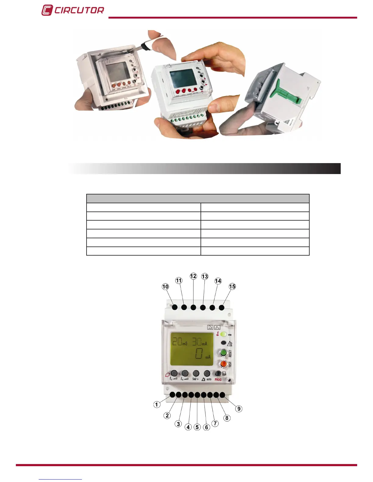
Figure 2: Installation of adapter accessory
3.3.- TERMINALS OF THE DEVICE
Table 3:Terminal description RGU-10�
Terminals of the device
1: Voltage input ON/OFF external L 9: Toroid current input 1S2
2: Voltage input ON/OFF external N 10: Power supply voltage input A1
4: Output common contact pre-alarm 11: Power supply voltage input A2
5: NC output contact pre-alarm 13: NO output contact trip
6: NO output contact pre-alarm 14: NC output contact trip
8: Toroid current input 1S1 15: Output common contact trip
Note: Terminals 3, 7 and 12 are free.
Figure 3: RGU-10 terminals�
 Loading...