17
If the rommon 1> prompt appears, your system has booted in ROM monitor mode. For information on using ROM
monitor, refer to the “Troubleshooting and Maintenance” module in the online Cisco 1800 series software
configuration documentation at the following URL:
http://www.cisco.com/univercd/cc/td/doc/product/access/acs_mod/1800/sw/index.htm
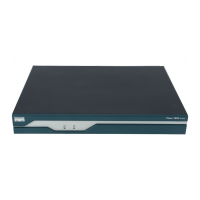
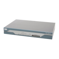
Verify the Front Panel LED Indications
The indicator LEDs described in Table 3 provide power, activity, and status information.
Verify the Hardware Configuration
Verify the router hardware configuration by entering the following commands:
• show version—Displays the system hardware version; the installed software version; the names and sources of configuration
files; the boot images; and the amount of installed DRAM, NVRAM, and flash memory.
• show diag—Lists and displays diagnostic information about the installed controllers, interface processors, and port
adapters. Typical examples are network modules, interface cards (WICs, VWICs, HWICs) and advanced integration
modules (AIMs).
7 Interface Numbering
Each individual interface (port) on a Cisco 1841 router is identified by a number. A Cisco 1841 router contains the following
wide-area network (WAN) and local-area network (LAN) interface types:
• Two onboard Fast Ethernet LAN interfaces
• Two slots in which you can install WICs, VWICs (data only), and HWICs
The numbering format for the slots is
interface-type 0/slot-number/port-number. Table 4 summarizes the interface numbering.
Table 3 LED Indicators
LED Color Description Location
SYS PWR Green Router has successfully booted up and the software is functional. This LED blinks
while booting or in the ROM monitor.
Front
SYS ACT Green Blinking when any packets are transmitted or received on any WAN or LAN, or when
monitoring system activity.
Front
CF Green On when compact flash memory is busy. Do not remove CompactFlash memory card
when this light is on.
Back
FDX (FE 0) Green On indicates full-duplex operation. Off indicates half-duplex operation. Back
100 (FE 0) Green On indicates a 100-Mbps link. Off indicates a 10-Mbps link. Back
Link (FE 0) Green On when the router is correctly connected to a local Ethernet LAN through Ethernet
port 0.
Back
FDX (FE 1) Green On indicates full-duplex operation. Off indicates half-duplex operation. Back
100 (FE 1) Green On indicates a 100-Mbps link. Off indicates a 10-Mbps link. Back
Link (FE 1) Green On when the router is correctly connected to a local Ethernet LAN through Ethernet
port 1.
Back
AIM Green On indicates presence of an AIM in the internal AIM slot. Back

 Loading...