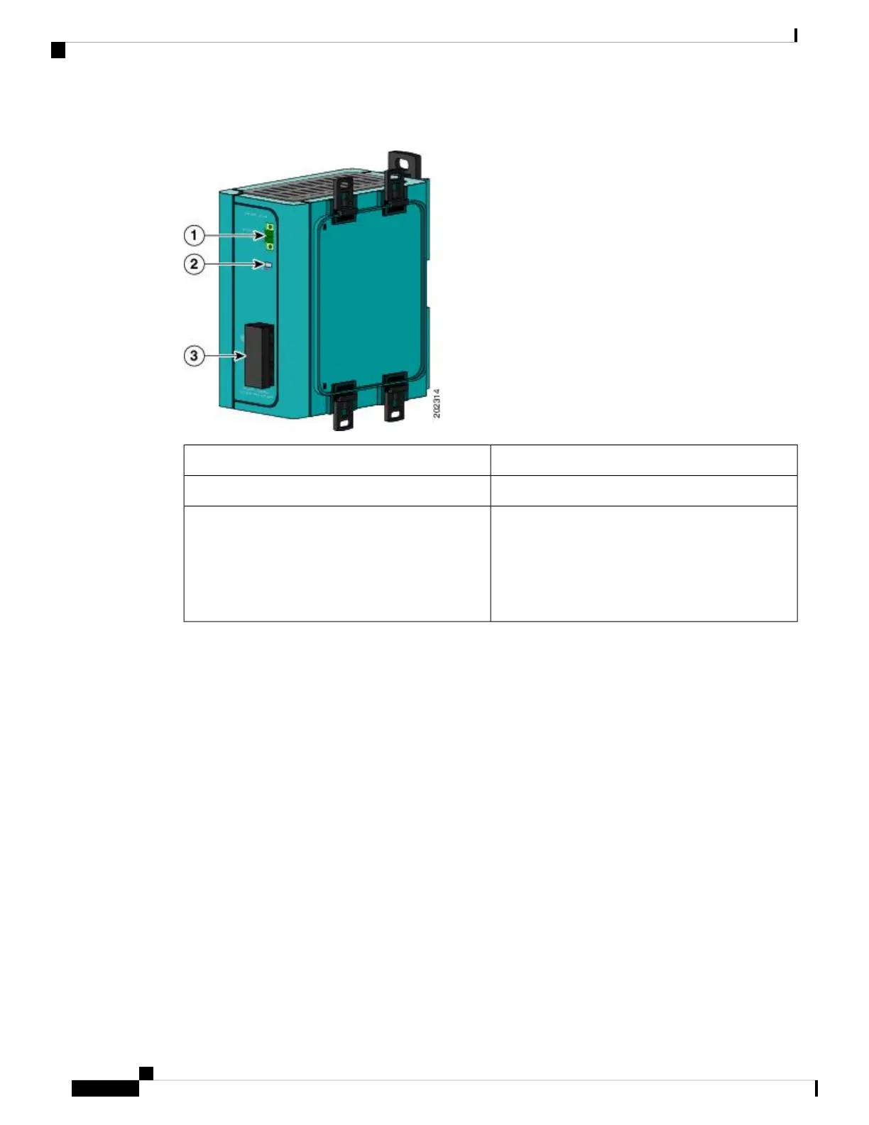
Figure 2: AC-Input Power Supply (PWR-IE50W-AC= Shown)
DC out connector1
STATUS LED2
Source AC terminal block (Cover shown installed)
The source AC terminal block shown in
the illustration is replaced by an IEC C14
appliance connector on the
PWR-50W-AC-IEC= power supply.
Note
3
Connecting the Router to the DC Source.
To connect the IR809 to the DC output, you will need to use a length of twisted pair along with connectors
on both ends. The twisted pair should be sized to handle at least 1 Amp at 24VDC. Details on the connector
and pin-outs for the IR809 side are found earlier in this guide at Wiring the DC Power and Alarm Connections.
The PWR-IE50W-AC power source comes with a DC clip that can be reused to connect to the IR809.
Disassemble the DC clip to expose the 2 pin and 4 pin connectors, as shown in the following diagram.
Connecting the Router
6
Connecting the Router
Connecting the Router to the DC Source.