Do you have a question about the Cisco 8200 Series and is the answer not in the manual?
Overview of the Cisco 8200 Series Routers, their architecture, and key features.
Essential safety guidelines to prevent personal injury and equipment damage during installation.
Details on regulatory compliance and safety approval requirements for Cisco 8000 Series Routers.
Warning regarding potential exposure to invisible laser radiation from optical connections.
Cautionary information about hazardous voltage and energy present on power terminals.
Procedures and precautions to prevent damage to sensitive components from static electricity.
Specific warnings and regulatory compliance statements relevant to NEBS environments.
General guidelines for preparing the site and environment for successful router installation.
List of essential tools and equipment required for the Cisco 8200 Series Routers installation.
Information on the contents of the accessory kit, including PIDs and necessary components.
Guidance on preparing the installation site, including essential grounding procedures.
Instructions for personnel to follow to ensure safety and prevent static discharge before installation.
Steps for preparing a standard 19-inch rack for the installation of the Cisco 8200 Series Router.
Specifications for required clearances around the chassis for optimal airflow and maintenance.
Procedures for mounting the Cisco 8200 Series Router chassis in both 4-post and 2-post racks.
Detailed instructions for correctly grounding the router chassis for electrical safety and stability.
Step-by-step guide for connecting the router chassis to an AC power source.
Step-by-step guide for connecting the router chassis to a DC power source.
Best practices for connecting network devices using optical modules and RJ-45 connectors.
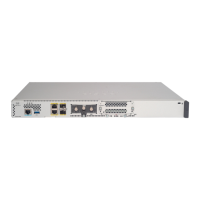
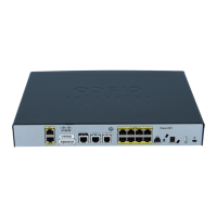
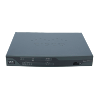
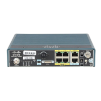
Detailed description of the front and rear interfaces, including port types and functions.
Instructions for establishing a local management connection using a console terminal.
Steps to perform the initial configuration, including setting up IP addresses and passwords.
Guidance on connecting the management Ethernet port for out-of-band network management.
Procedures for installing and removing QSFP transceiver modules from the router.
Instructions for connecting various interface ports to network devices for connectivity.
Methods and commands to verify the successful installation and operational status of the chassis.
Procedure for safely removing and replacing fan modules without interrupting system operation.
Step-by-step instructions for replacing AC or DC power supply units in the router.
Overview of the status, synchronization, and GPS LEDs located on the chassis front and back.
Description of the Status LED on each fan tray module indicating fan operation.
Explanation of the Status LED on each power module and its meaning.
Details on the LEDs for each port, indicating administrative status and link activity.
| Dimensions | Varies by model |
|---|---|
| Operating Temperature | 0°C to 40°C (32°F to 104°F) |
| Storage Temperature | -40°C to 70°C (-40°F to 158°F) |
| Power Supply | Redundant power supplies |
| Operating System | Cisco IOS XR |
| Security Features | ACLs |
| Virtualization | Supports virtualization features |
| Product Type | Router |
| Interfaces | 10GE, 40GE, 100GE, 400GE |
| Ports | Varies by model |
| Routing Protocols | BGP, OSPF, IS-IS |
| Weight | Varies by model |
| Humidity | 5% to 95% noncondensing |