Connect DC Power to the Chassis
The chassis relies on the protective devices in the building installation to protect against short circuit,
overcurrent, and ground faults. Ensure that the protective devices comply with local and national electrical
codes.
Caution
Step 1 Verify that the correct fuse panel is installed in the top mounting space.
Step 2 Ensure that the DC circuit is powered down (either breaker turned off or fuse pulled) and proper lockout tag out procedures
are followed. Use the cable (PID: 72-100992-02) supplied with the power supply. If you prefer to use your own cable,
the cable size must be 6 AWG.
Step 3 Dress the power according to local practice.
Step 4 Connect the office battery and return cables according to the fuse panel engineering specifications.
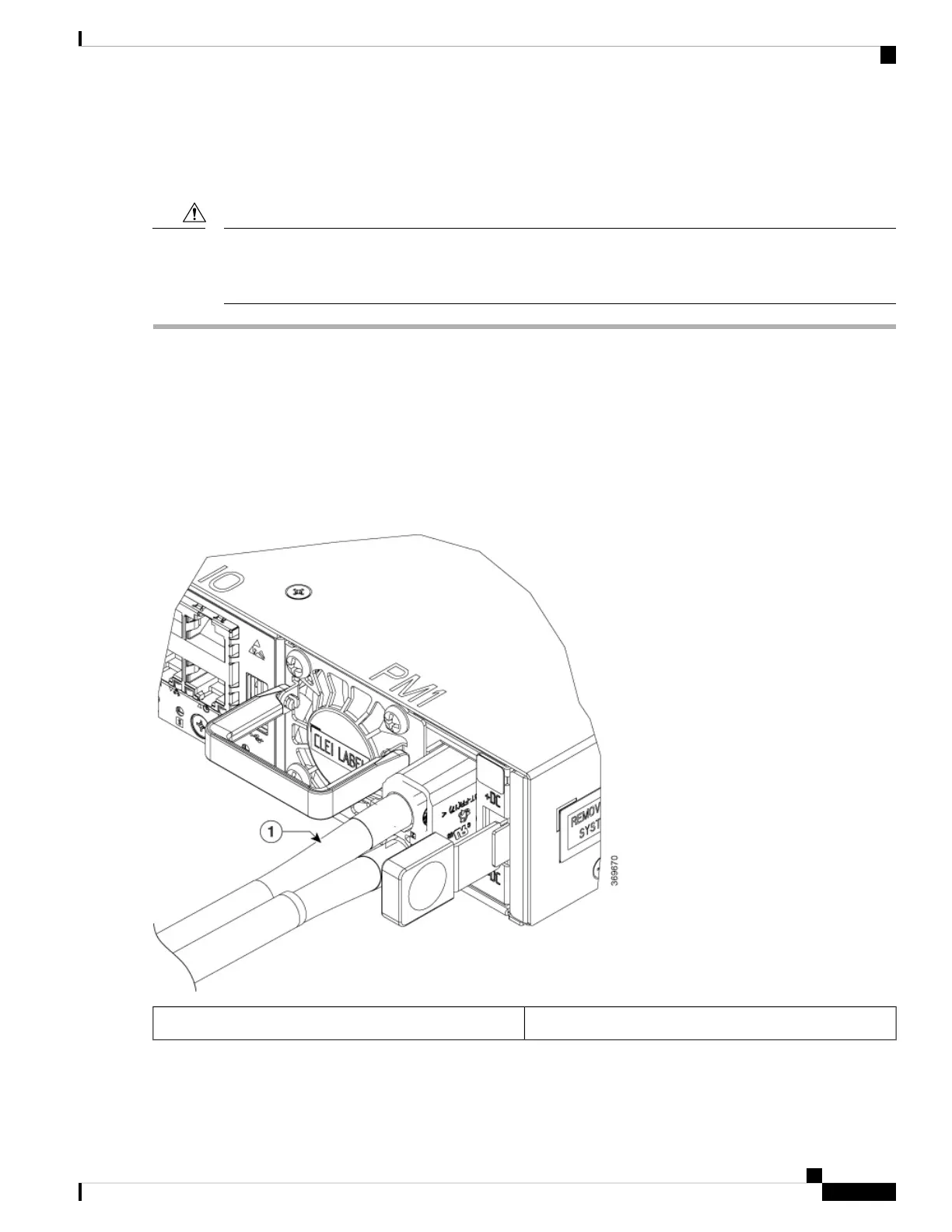
Step 5 Insert the DC connector into the DC receptacle on the power supply.
Figure 11: Connecting DC Power
DC power cable1
Step 6 Ensure that the locking mechanism has engaged to secure the cable.
Hardware Installation Guide for Cisco 8200 Series Routers
23
Installing the Chassis
Connect DC Power to the Chassis
 Loading...