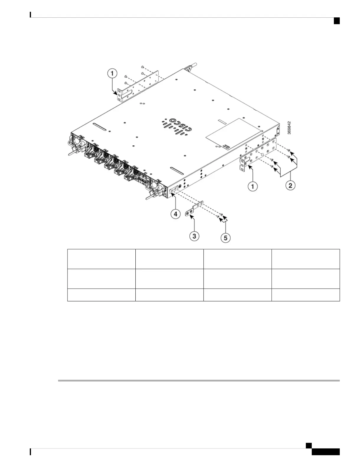
Figure 8: Figure 6: Rack-Mount Brackets on Cisco 8201 Router—Port-Side Exhaust
Remove grounding cover
label
4Rack-mount brackets1
M4 x 6-mm Phillips
flat-head screws
5M4 x 6-mm Phillips
flat-head screws
2
Grounding cover plate3
d) Repeat Steps 1b and 1c with the other rack-mount bracket on the other side of the router.
Step 2 Install the router onto the 2-post rack:
a) With the assistance of another person, lift the router into position between the two rack posts.
b) Move the router until the rack-mount brackets come in contact with two rack posts.
c) Hold the chassis at a level position while the second person inserts two screws (12-24 or 10-32, depending on the
rack type) in each of the two rack-mount brackets (a total of four screws) and into the cage nuts or threaded holes in
the vertical rack-mounting rails.
d) Tighten the 10-32 screws to 20 in-lb (2.26 N.m) or tighten the 12-24 screws to 30 in-lb (3.39 N.m).
Hardware Installation Guide for Cisco 8200 Series Routers
19
Installing the Chassis
Rack-Mount the Chassis in a 2-Post Rack
 Loading...