2-43
Cisco Integrated Services Router Hardware Installation Guide
Chapter 2 Installing the Router
Installing the Cisco 860, 880, 890 ISR
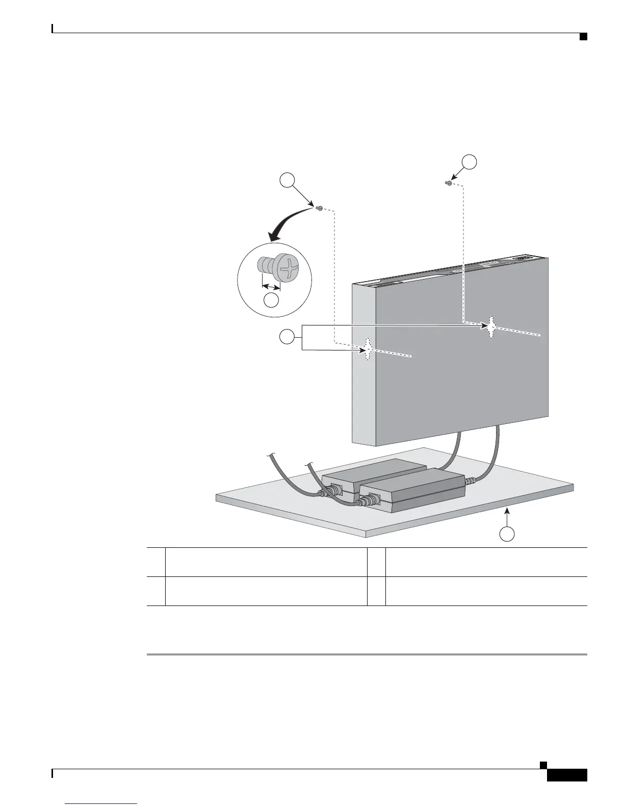
Step 3 Hang the router on the screw without forcibly pushing towards the wall side. The screw head may
damage the protection wall inside. Place the power adapter on a nearby horizontal surface. See
Figure 2-38.
Figure 2-38 Router Mounted on the Wall
Step 4 Connect the chassis to a reliable earth ground. For the chassis ground connection procedures, see the
“Installing Cisco 890 Series in a Rack” section on page 2-52.
1 Two number-10 wood screws mounted on the
wall
3 Horizontal surface on which to place the
power adapter
2 Wall-mount holes 4 Distance between the screw head and the wall,
1/8 in. (0.32 cm)
 Loading...