Rear Panel
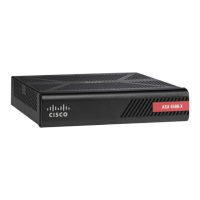
The following figure shows the rear panel of the ASA 5506-X. The 5506W-X has an identical rear panel.
Figure 5: ASA 55-6-X and 5506W-X Rear Panel
Power cord socket
The chassis power-supply socket. See
Power Supply Modules, on page 13 for
more information about the chassis
power supply.
The ASA is powered on when
you plug in the AC power
supply.
Note
2Status LEDs
The locations and meanings of the status
LEDs are described in LEDs, on page
8.
1
4
Management port
A Gigabit Ethernet interface restricted
to network management access only.
Connect with an RJ-45 cable.
Network data ports
Eight Gigabit Ethernet RJ-45 (8P8C)
network I/O interfaces. The ports are
numbered (from left to right) 1, 2, 3, 4,
5, 6, 7, 8. Each port includes a pair of
LEDs, one each for connection status
and link status. The ports are named and
numbered Gigabit Ethernet 1/1 through
Gigabit Ethernet 1/8. See Network
Ports, on page 11 for additional
information.
3
USB port
A standard USB Type A port is
provided that allows the attachment of
an external device, such as mass storage.
See Internal and External Flash Storage,
on page 12 for additional information.
6Console ports
Two serial ports, a mini USB Type B,
and a standard RJ-45 (8P8C), are
provided for management access via an
external system. See Console Ports, on
page 11 for additional information.
5
Cisco ASA 5506-X, ASA 5506W-X, and ASA 5506H-X Hardware Installation Guide
6 Online Only
Overview
Rear Panel
 Loading...