Maintenance and Upgrade Procedures for the ASA 5500-X
Remove and Replace the Chassis Cover
Cisco ASA 5512-X, ASA 5515-X, ASA 5525-X, ASA 5545-X, and ASA 5555-X Hardware Installation Guide
50
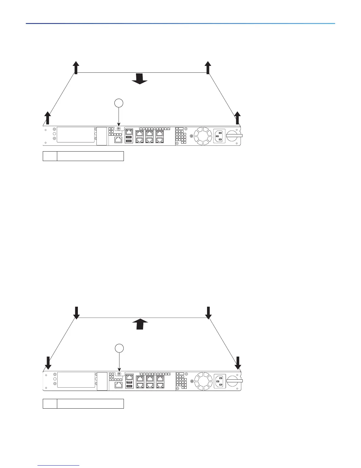
Figure 1 Removing the Chassis Cover
3. Remove the chassis cover by placing your hand on top of the chassis lid, pressing down firmly, and pushing
the cover toward the rear of the chassis. (See Figure 1.)
4. Place the cover in a safe place.
Replace the Chassis Cover
Caution: Do not operate the ASA without the chassis cover installed. The chassis cover protects the internal
components, prevents electrical shorts, and provides proper air-flow for cooling the electronic components.
To replace the chassis cover, perform the following steps.
Procedure
1. Place the chassis on a secure surface with the front panel facing you.
2. Lower the front of the chassis cover onto the chassis, slide it forward until it fits into place, and tighten the
thumbscrew to secure the chassis cover. (See Figure 2.)
Figure 2 Replacing the Chassis Cover
3. Re-install the chassis on a rack.
4. Re-install the network interface cables.
1 Thumbscrew
1 Thumbscrew
 Loading...