1-11
Cisco ASR 920 Series Aggregation Services Router Hardware Installation Guide
OL-32751-01
Chapter 1 Cisco ASR 920 Series Aggregation Services Router Overview
Cisco ASR 920 Router Features
Power Supply Unit LEDs
Each power supply unit has a corresponding LED on the front panel.
System–Interface LED Behavior
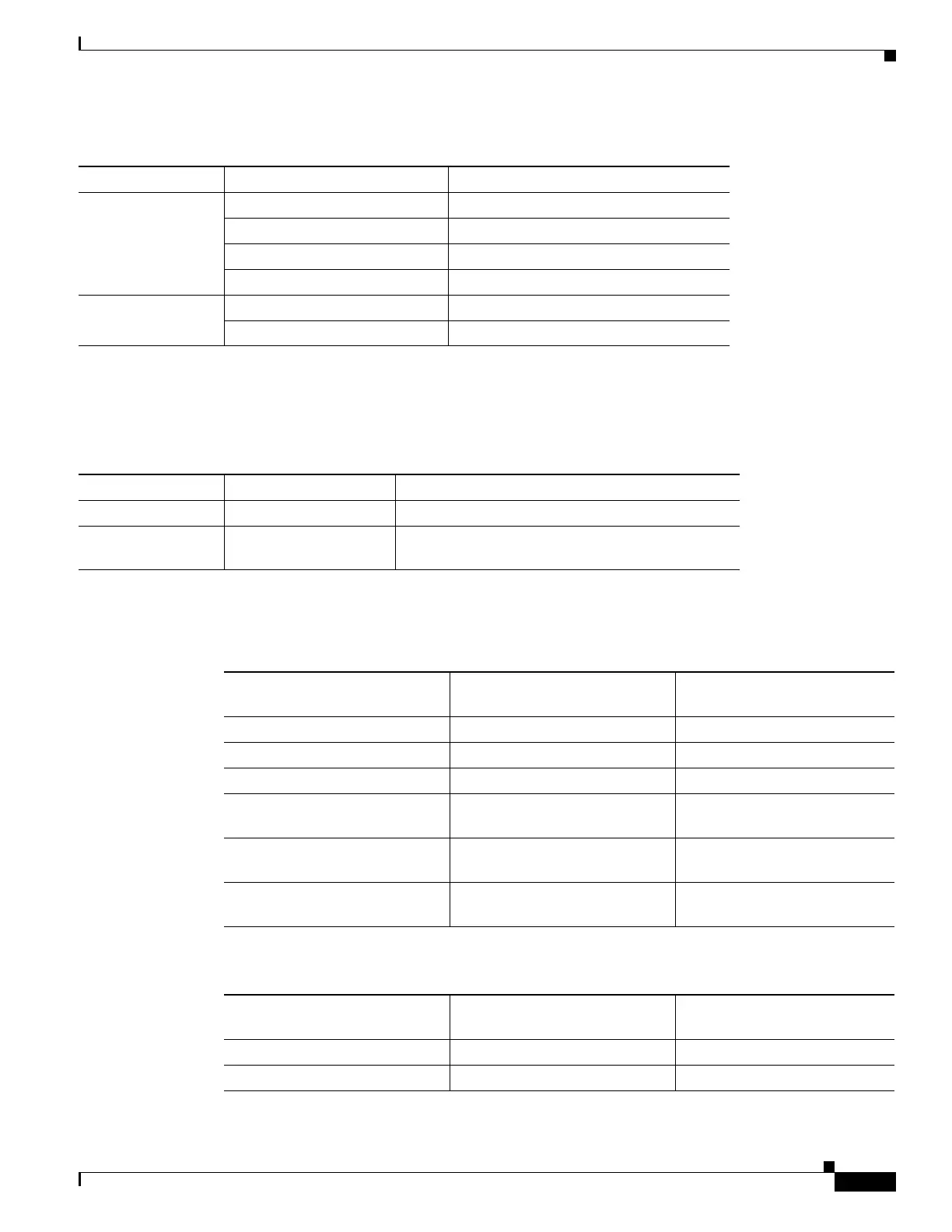
Table 1-7 RJ-45 LED Indication
LED LED State Indication
Left Green Link up in 10/100/1000Base-T
Blinking Green Activity in 10/100/1000Base-T
Yellow Fault/Error
Off Link down
Right Green Link up in full duplex
Off Link up in half duplex
Table 1-8 PSU LED Indication
LED LED State Indication
OK Green Power Supply is working and 12V output is alright.
Red 12V output failure (Either input not present or fault
in the power supply unit).
Table 1-9 1G Copper and 1G SFP LED Indication
Event
1G Copper Port LEDs
(Link/Duplex) 1G SFP Port LEDs
ROMMON Off/Off Off
IOS Shut Off/Off Off
IOS No shut (cable disconnect) Yellow/Off Yellow
IOS No shut (cable connect)
(media-type RJ-45)
Green/Green Off
IOS No shut (cable connect)
(media-type SFP)
Off/Off Green
IOS No shut (cable connect)
(media-type auto)
Off/Off Green
Table 1-10 Dual Rate and Management Port LED Indication
Event Dual Rate (1G/10G) Port LEDs
Management Port LEDs
(Link/Duplex)
ROMMON Off Green/Off
IOS Shut Off Off/Off
 Loading...