L
Lisa GreenAug 3, 2025
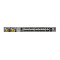
What does Major Alarm mean on Cisco ASR-920-12SZ-A Network Router?
- JJames BushAug 3, 2025
A Major Alarm on a Cisco Network Router means that an environmental sensor threshold (like voltage or temperature) has exceeded a major level.