EasyManua.ls Logo

Cisco ATA Series User Manual

Cisco ATA Series
8 pages
To Next Page IconTo Next Page
Page #1 background imageLoading...
Page #1 background image
Get Started with Your New ATA
Your New ATA, on page 1
Devices Associated with Your ATA, on page 4
Install Your New ATA, on page 4
Mount Your ATA, on page 6
Supported ATA Call Features, on page 7
Your New ATA
Your analog telephone adapter (ATA) allows you to connect an analog device, such as an analog phone or
fax machine, to your network. The connected device can then function like the IP phones in your network.
Your new analog telephone adapter (ATA) has two interfaces:
Two RJ11 ports for analog devices
A RJ45 port for Ethernet
Light-emitting diodes (LEDs) on the ATA provide status.
You'll perform these tasks:
Install your ATA with the components in the box.
Cisco ATA 191 Hardware
The ATA 191 and ATA 192 are compact, easy to install devices.
The unit provides these connectors:
5V DC power connector.
Two RJ-11 FXS (Foreign Exchange Station) ports—Your ATA has two RJ-11 ports that work with any
standard analog phone device. Each port supports either voice calls or fax sessions, and both ports can
be used simultaneously.
One WAN network port—An RJ-45 10/100BASE-T data port to connect an Ethernet-capable device to
the network.
Get Started with Your New ATA
1
Question and Answer IconNeed help?

Do you have a question about the Cisco ATA Series and is the answer not in the manual?

Cisco ATA Series Specifications

General IconGeneral
ProtocolsSIP, SCCP
Voice CodecsG.711, G.726
Fax SupportT.38
FXS Ports1 or 2
Network InterfacesEthernet
Operating Temperature32°F to 104°F (0°C to 40°C)
Storage Temperature-4°F to 140°F (-20°C to 60°C)
Humidity10% to 90% non-condensing

Summary

ATA 191 Top Panel

Top Panel LEDs

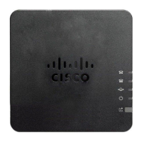
Details the status indicators on the ATA's top panel, including Power, Network, Phone 1, and Phone 2 LEDs.

ATA 191 Back Panel

Problem Report Tool (PRT)

Information on the Problem Report Tool button and its associated LED for generating and sending diagnostic reports.

Back Panel Ports

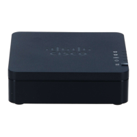
Details the connectors on the ATA's back panel: RESET, PHONE 1, PHONE 2, NETWORK, and DC 5V POWER.

Install Your New ATA

Installation Procedure

Step-by-step guide for connecting the ATA to your network, analog device, and power source.

Mount Your ATA

Desktop Placement

Instructions for placing the ATA unit on a flat surface near an electrical outlet.

Wall Mounting

Guidance on mounting the ATA unit onto a wall using appropriate hardware and slots.

Related product manuals