Do you have a question about the Cisco ATA Series and is the answer not in the manual?
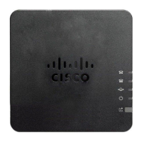
Details the status indicators on the ATA's top panel, including Power, Network, Phone 1, and Phone 2 LEDs.
Information on the Problem Report Tool button and its associated LED for generating and sending diagnostic reports.
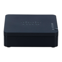
Details the connectors on the ATA's back panel: RESET, PHONE 1, PHONE 2, NETWORK, and DC 5V POWER.
Step-by-step guide for connecting the ATA to your network, analog device, and power source.
Instructions for placing the ATA unit on a flat surface near an electrical outlet.
Guidance on mounting the ATA unit onto a wall using appropriate hardware and slots.