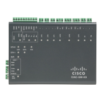
Figure 21: Power Connector Pin-Outs
DescriptionNamePIN Number
DC Power Negative InputDC In -1
DC Power Negative InputDC In -2
DC Power Positive InputDC In +3
DC Power Positive InputDC In +4
To connect the DC power connections on the terminal gateway, follow these steps:
Locate the power connector in the accessory package.
In the connector, the pins from left to right are:
1—Negative DC power connection
2— Negative DC power connection
3— Positive DC power connection
4— Positive DC power connection
1
Hardware Installation Guide for the Cisco 1100 Terminal Gateway
30
Install and Connect the Router
Connecting to DC Power

 Loading...


