Chapter 3 Installing the Switch
Connecting AC Power to the Switch
3-10
Catalyst 4900 Series Switch Installation Guide
78-18039-02
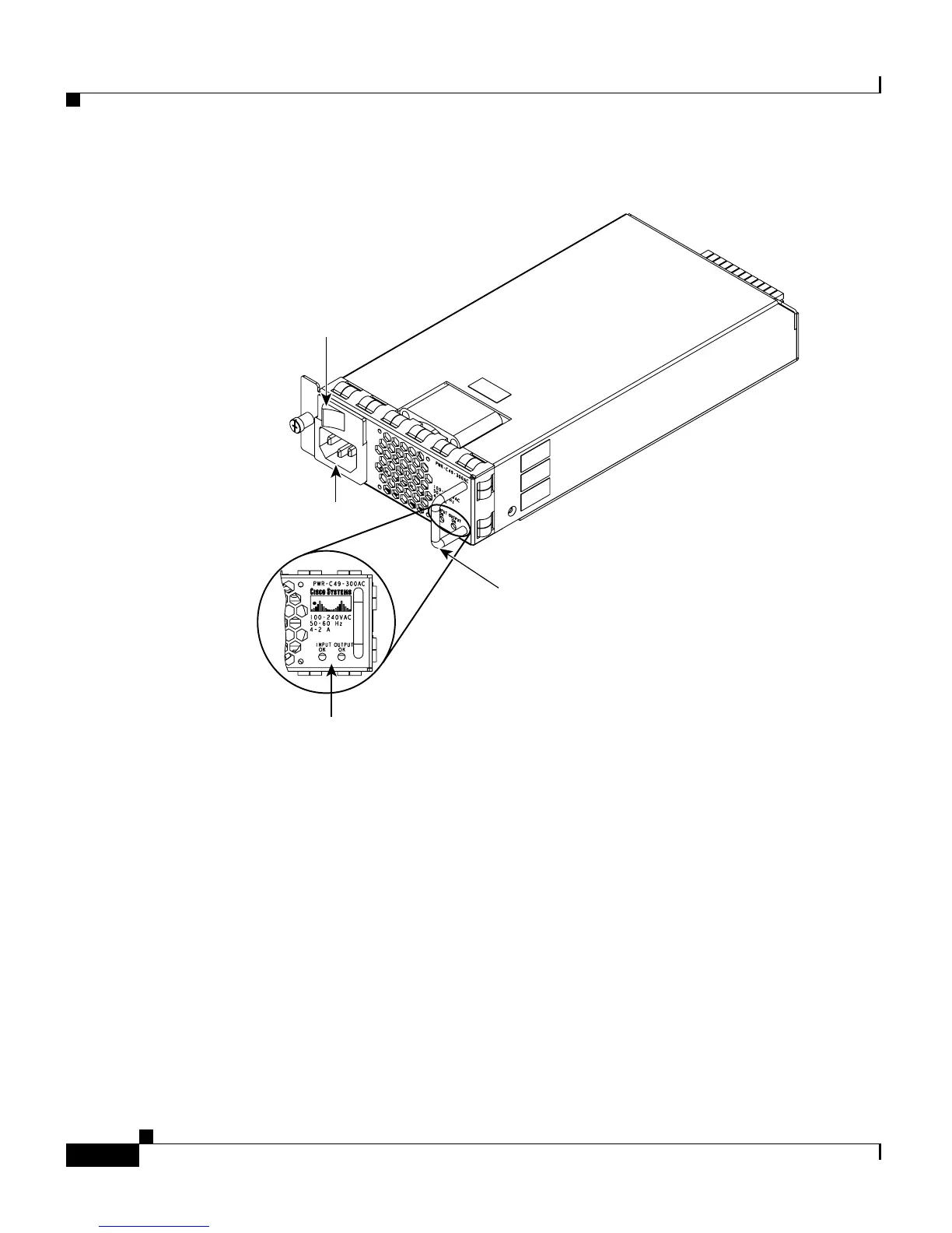
Figure 3-5 AC Power Supply
Step 3 Connect the other end of the power cords to an AC-power input source. If both
power supplies will be used, make sure they are on different circuits.
Step 4 Turn the power switches to the ON position.
Step 5 Verify power supply operation by looking at the front panel power supply LEDs:
• The PS1 or PS2 LED is green when the power supply and fans are functioning
normally.
• The PS1 or PS2 LED is red when the power supply is not functioning
normally. The on/off switch may be set to off while the power supply is
plugged in, or the power supply may be defective and not providing DC
power to the switch. There may also be a fan failure.
• The PS1 or PS2 LED is off when there is no power supply installed.
Status LEDs
AC power plug
Handle
On/off switch
120696
 Loading...


