Chapter 3 Installing the Switch
Connecting DC Power to the Switch
3-12
Catalyst 4900 Series Switch Installation Guide
78-18039-02
Step 1 Prior to connecting the power supply to a power source, ensure that all of the site
power and grounding requirements described in
Chapter 2, “Site Planning,” have
been met and the chassis is properly grounded as described in the “Grounding
Requirements” section on page 2-6.
Step 2 Remove the safety cover from the power terminal.
Step 3 Connect the power supply ground terminal to earth ground.
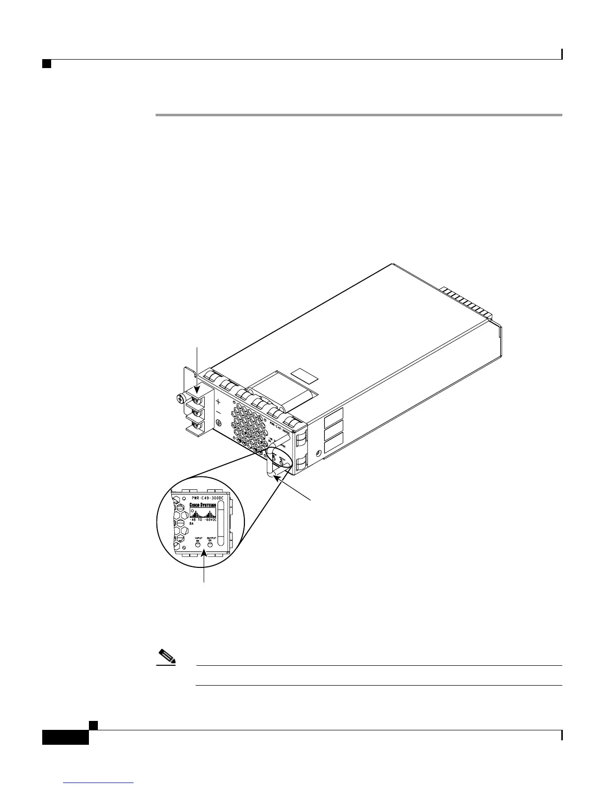
Figure 3-6 DC Power Supply
Step 4 Connect the positive and negative power cables into the power supplies using a
number 2 Phillips screwdriver.
Note The DC power cables may use AWG #10 to AWG #12 wire.
Status LEDs
Handle
DC input
terminals
120697