Do you have a question about the Cisco Catalyst 9200 Series and is the answer not in the manual?
Pinch the release handle and slide the fan module out. Replace within 5 minutes to avoid overheating.
Insert the module firmly into the slot, ensuring it is flush with the rear panel. A green LED indicates operation.
| Category | Switch |
|---|---|
| Stacking Bandwidth | 160 Gbps |
| Layer | Layer 2 and Layer 3 |
| Operating System | Cisco IOS XE |
| Operating Temperature | 0°C to 45°C (32°F to 113°F) |
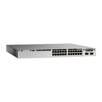
| Series | Cisco Catalyst 9200 Series |
| Ports | 24 or 48 Ethernet ports |
| Switching Capacity | Up to 176 Gbps |
| PoE | PoE, PoE+, and UPOE |
| Stacking | StackWise-160 |
| Memory | 4 GB DRAM, 4 GB Flash |
| Network Management | Cisco DNA Center, WebUI, CLI |
| Security Features | 802.1X, TrustSec, MACsec |
| Warranty | Limited Lifetime Warranty |
| Dimensions | 1.73 x 17.5 x 11.3 in. (4.4 x 44.5 x 28.8 cm) |




 Loading...