Do you have a question about the Cisco Catalyst 9400 Series and is the answer not in the manual?
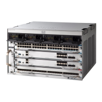
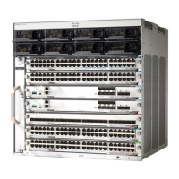
Details the different Cisco Catalyst 9400 Series switch models available.
Provides an overview of the fan tray assembly, its function, and specifications.
Describes the available power supply modules and their features.
Outlines essential location planning and site requirements for successful switch operation.
Covers temperature, airflow, humidity, and altitude for optimal performance.
Details electrical safety, grounding, ESD prevention, and power source requirements.
Guidelines for cable management and installing the chassis in equipment racks.
Covers installing the switch as shipped and with shelf brackets.
Detailed steps for physically mounting the switch chassis into an equipment rack.
Procedures for establishing system ground and attaching ESD straps.
Steps to verify that the switch chassis is installed correctly and all components are seated.
Procedures for removing and installing fan trays from the front and rear of the chassis.
Instructions for removing and installing AC-input and DC-input power supply modules.
Steps to verify that the system software boots successfully after initial power-on.
Guide to interpreting LEDs on various modules to diagnose startup issues.
Procedures and Cisco IOS commands for diagnosing power supply module issues.
Steps to diagnose fan tray assembly problems, including checking LEDs and airflow.
Guidance on identifying and resolving high temperature alarms, often related to air filters.
Steps for diagnosing issues with supervisor modules, including LED indicators and seating.
Physical and environmental specifications for Catalyst 9400 Series chassis models.
Technical details for AC and DC input power supply modules, including capacities and voltage.
Weights for various chassis, supervisor, switching, and power supply modules.
Explains the meaning of STATUS and LOCATE LEDs on the fan tray.
Details the meaning of INPUT, OUTPUT, and FAIL LEDs for power supply modules.
Describes the STATUS, LOCATE, and PORT LINK LEDs for switching modules.
Explains the STATUS, LOCATE, ACTIVE, and MANAGEMENT LEDs for supervisor modules.
Instructions for initial switch setup via the Web User Interface.
Steps for initial switch configuration using the Command Line Interface.
Procedure to configure network parameters in ROMMON mode for initial setup.
Guides for installing and removing USB device drivers for console connection.
| Series | Catalyst 9400 Series |
|---|---|
| Form Factor | Rack-mountable |
| Operating System | Cisco IOS XE |
| Uplink Options | 40G and 100G uplinks |
| Stacking | Not supported |
| Layer Support | Layer 2 and Layer 3 |
| Operating Temperature | 0°C to 40°C (32°F to 104°F) |
| Storage Temperature | -40°C to 70°C (-40°F to 158°F) |
| Humidity | 5% to 90% noncondensing |
| Power Supply Options | AC and DC power supplies |
| Redundancy | Power supply, supervisor engine |
| Modular Slots | 7 or 10 |
| MAC Address Table Size | 256, 000 |
| Security Features | ACLs, TrustSec, MACsec |
| Management | CLI, SNMP, NETCONF, RESTCONF, Cisco DNA Center |



 Loading...