Do you have a question about the Cisco Catalyst 9404R Switch and is the answer not in the manual?
Overview of Catalyst 9404R, 9407R, and 9410R switch variants.
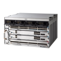
Details of the Catalyst 9404R Switch chassis and components.
Details of the Catalyst 9407R Switch chassis and components.
Details of the Catalyst 9410R Switch chassis and components.
General safety warnings applicable to the installation process.
Essential site requirements for successful switch installation.
Sensitivity to power variations and protection measures.
Importance of proper grounding and recommended practices.
Guidelines for safe handling of electrical equipment.
Measures to prevent damage from electrostatic discharge (ESD).
Requirements for AC input power, branch circuits, and UPS.
Specifications and guidelines for mounting the chassis in a rack.
Warnings and overview of the overall switch installation process.
Procedure for rack-mounting the chassis as shipped.
Procedure for installing the switch using optional shelf brackets.
Instructions for physically mounting the chassis into the rack.
Steps to attach the grounding lug and cable to the grounding pad.
Procedure for correctly attaching an ESD wrist strap for protection.
Steps to verify the correct installation of the switch chassis.
Procedures for removing and installing the fan tray assembly.
How to enable service mode using Cisco IOS commands for fan tray servicing.
Steps to remove the fan tray from the front of the chassis.
Steps to install the fan tray into the chassis from the front.
Steps to remove the fan tray assembly from the rear of the chassis.
Procedures for removing and installing AC-input power supply modules.
Using LEDs to diagnose and isolate startup issues.
Steps to diagnose and resolve power subsystem problems.
Steps to diagnose and resolve fan tray assembly issues.
Diagnosing and resolving issues with switching modules.
Diagnosing and resolving problems with supervisor modules.
Steps to resolve issues preventing console port connectivity.
Assigning IP address and network configuration details.
Guided process for initial switch configuration through prompts.
| Product Type | Modular Switch |
|---|---|
| Form Factor | Rack-mountable |
| Slot Capacity | 4 |
| Management | Cisco IOS XE |
| Model | Catalyst 9404R |
| Product Series | Catalyst 9400 Series |
| Uplink Ports | Varies by module |
| Downlink Ports | Varies by module |
| Supported Modules | C9400-LC-24XS, C9400-LC-48T, C9400-LC-48U |
| Power Supply | AC or DC |
| Power Supply Options | AC or DC |
| Redundancy | Power supply redundancy |
| Operating Temperature | 0 to 40 °C |
| Storage Temperature | -40 to 70 °C |
| Relative Humidity | 5% to 90% noncondensing |





 Loading...