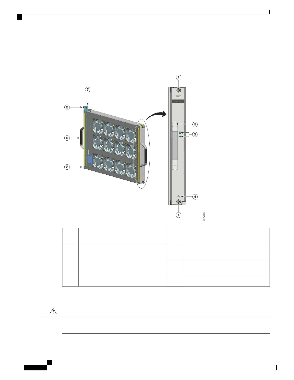
The following figure shows the C9407-FAN with the major components identified. The C9410-FAN has the
same features, and in addition, a fourth row of fans. The C9404-FAN has the same features but has only two
rows of fans.
Figure 1: Fan Tray Assembly
Front fan tray handle.5Captive installation screws on the front of the
fan tray.
1
Rear fan tray handle6Captive installation screws on the rear of the
fan tray.
2
Fan tray adapter7LEDs on the front panel. (The rear blue
beacon LED is not visible in this image)
3
--Fan tray RFID4
Operation
Do not operate the system if the fan tray assembly is removed or if it is not functioning properly. An
overtemperature condition can cause severe equipment damage or an unscheduled system shutdown.
Caution
Cisco Catalyst 9400 Series Switches Hardware Installation Guide
18
Product Overview
Operation