EasyManuals Logo

Cisco Catalyst 9400 Series User Manual

Cisco Catalyst 9400 Series
192 pages
To Next Page IconTo Next Page
To Previous Page IconTo Previous Page
Page #129 background imageLoading...
Page #129 background image
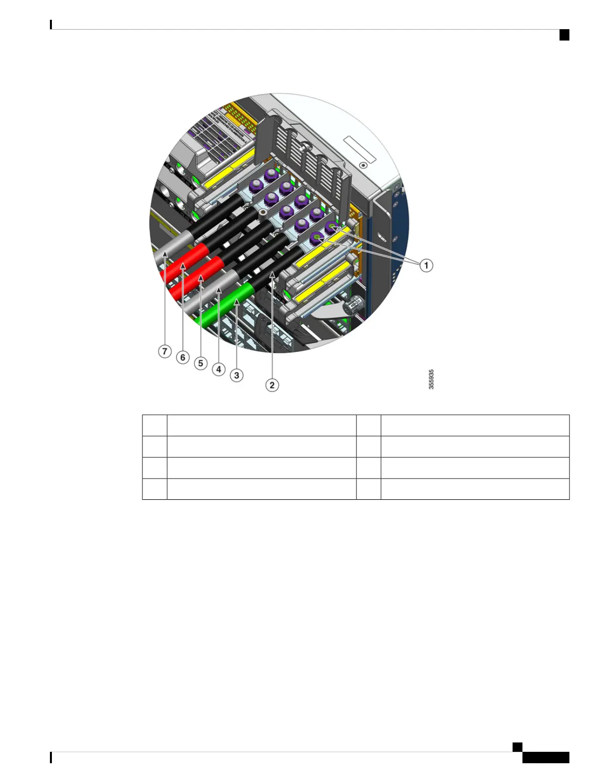
DC-input wire for positive circuit (+ B)5Lug secured with two nuts1
DC-input wire for positive circuit (+A)6Heat-shrink sleeve on all the wires2
DC-input wire for negative circuit (- A)7Grounding wire3
--DC-input wire for negative circuit (-B)4
Step 7 Close the terminal block cover and finger-tighten the captive installation screw (approximately 0.25 Nm).
Cisco Catalyst 9400 Series Switches Hardware Installation Guide
123
Removing and Replacing FRUs
Connecting the DC-Input Wires

Table of Contents

Other manuals for Cisco Catalyst 9400 Series

Questions and Answers:

Question and Answer IconNeed help?

Do you have a question about the Cisco Catalyst 9400 Series and is the answer not in the manual?

Cisco Catalyst 9400 Series Specifications

General IconGeneral
SeriesCatalyst 9400 Series
Form FactorRack-mountable
Operating SystemCisco IOS XE
Uplink Options40G and 100G uplinks
StackingNot supported
Layer SupportLayer 2 and Layer 3
Operating Temperature0°C to 40°C (32°F to 104°F)
Storage Temperature-40°C to 70°C (-40°F to 158°F)
Humidity5% to 90% noncondensing
Power Supply OptionsAC and DC power supplies
RedundancyPower supply, supervisor engine
Modular Slots7 or 10
MAC Address Table Size256, 000
Security FeaturesACLs, TrustSec, MACsec
ManagementCLI, SNMP, NETCONF, RESTCONF, Cisco DNA Center

Related product manuals