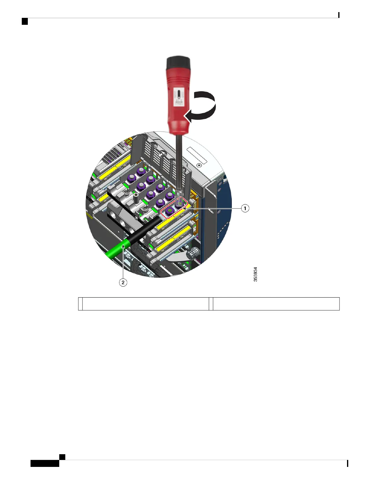
Grounding wire with heat-shrink sleeve2Lug secured with the two nuts1
Step 6 Attach the four DC-input power source cables similarly.
When facing the terminal block, the circuits are in the following order from left to right: negative (- A), positive
(+A), positive (+ B), and negative (-B).
-A and +A form one DC input, and + B and -B form another. Each DC input can be powered either from
separate sources, or a suitable single source.
Cisco Catalyst 9400 Series Switches Hardware Installation Guide
122
Removing and Replacing FRUs
Connecting the DC-Input Wires

 Loading...


