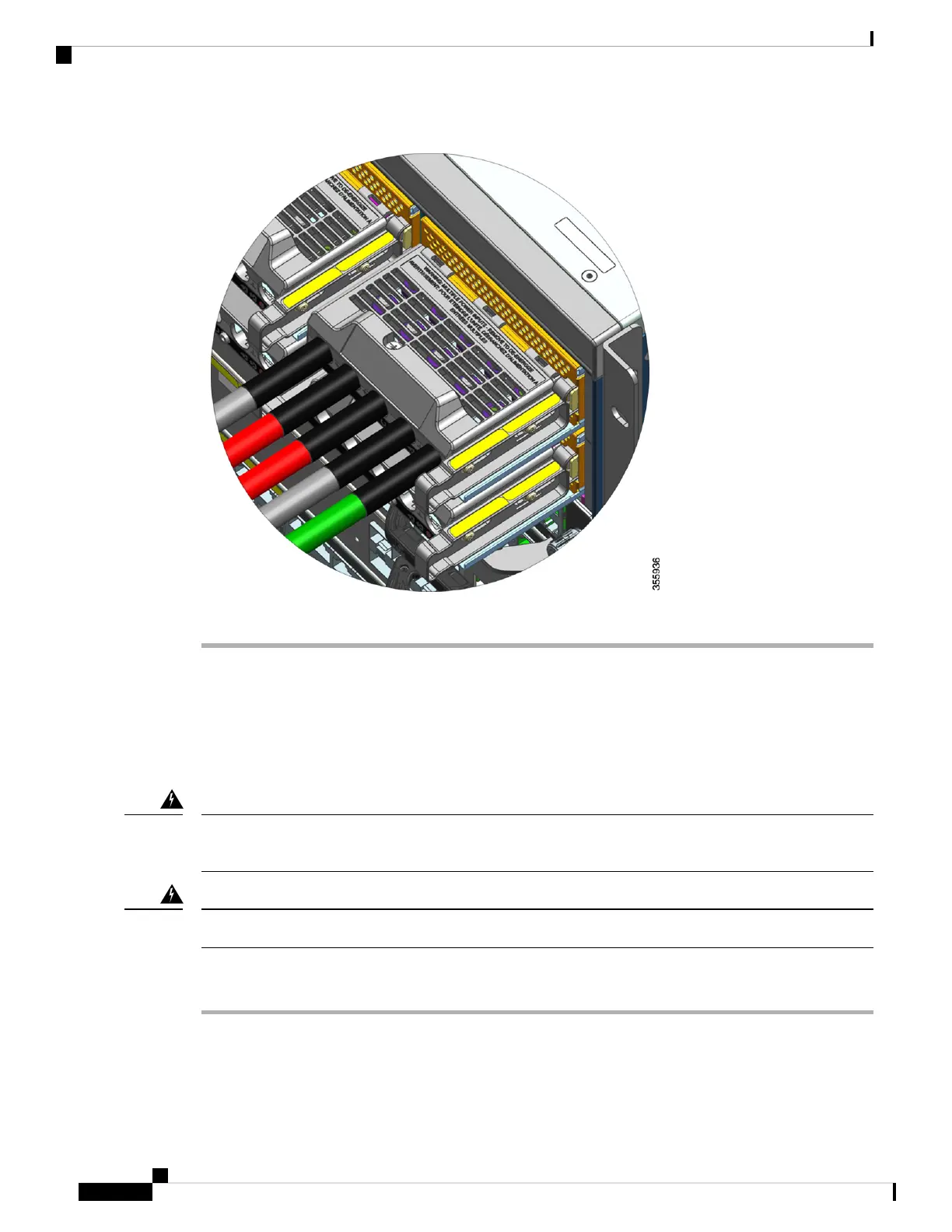
Powering Up a DC-Input Power Supply Module
After you have installed the power supply module in the chassis and connected the DC-input wires, follow
the steps described here to power up the module and verify that the module is installed correctly.
Before you begin
Only trained and qualified personnel should be allowed to install, replace, or service this equipment. Statement
1030
Warning
No user-serviceable parts inside. Do not open. Statement 1073
Warning
Procedure
Step 1 For the powered down circuits connected to the power supply modules, turn on the power at the circuit breaker.
The FAIL LED is illuminated for two to three seconds after DC input is applied through a circuit breaker.
Cisco Catalyst 9400 Series Switches Hardware Installation Guide
124
Removing and Replacing FRUs
Powering Up a DC-Input Power Supply Module

 Loading...


