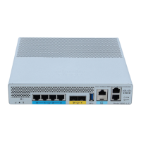
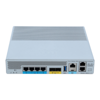
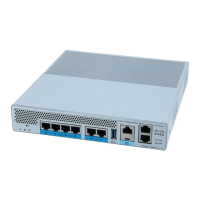
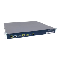
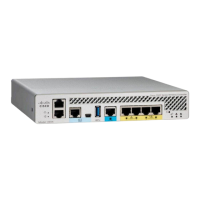
Figure 8: Attaching a Grounding Lug to the Chassis Ground Connector
Ground screws3Chassis ground lead wire1
Chassis ground connector holes4Grounding lug2
Step 3 Use the crimping tool to carefully crimp the wire receptacle around the wire. This step is required to ensure a proper
mechanical connection.
Step 4 Locate the chassis ground connector on the side of your chassis.
Step 5 Insert the two screws through the holes in the grounding lug.
The following figure shows how to attach a grounding lug to the chassis ground connector.
Figure 9: Attaching the Grounding Lug to the Ground Connector of the Cisco Catalyst 9800-40 Wireless Controller
Ground connector on the chassis3Chassis ground lug1
Ground symbol4Grounding screws2
Step 6 Use the Number 2 Philips screwdriver to carefully tighten the screws until the grounding lug is held firmly to the chassis.
Do not over tighten the screws.
Installing the Controller
13
Installing the Controller
Attaching a Chassis Ground Connection
 Loading...
