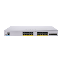
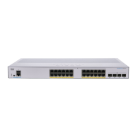
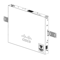
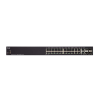
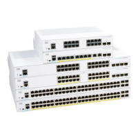
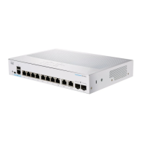
Models may differ within the CBS 350 series and this is just a representation of a model within the series.
Note
• Console port with RJ-45 and mini-USB connectors. The console connects a serial cable to a computer
serial port so that it can be configured using a terminal emulation program.
• USB Port—The USB port connects the switch to a USB device so that you can save and restore the
configuration files, firmware images, and SYSLOG files through the connected USB device.
• RJ-45 Ethernet Ports—The RJ-45 Ethernet ports connect network devices, such as computers, printers,
and access points, to the switch.
• SFP+ Port (if present)—The small form-factor pluggable plus (SFP+) are connection points for modules
so that the switch can link to other switches. These ports are also commonly referred to as mini 10GigaBit
Interface Converter ports. The term SFP+ is used in this guide.
• The SFP+ ports are compatible with the following Cisco SFP 1G optical modules MGBSX1, MGBLX1,
MGBLH1, MGBT1, as well as other brands.
• The Cisco SFP+ 10G optical modules that are supported in the Cisco switches are: SFP-10G-SR,
SFP-10G-LR, SFP-10G-SR-S, and SFP-10G-LR-S.
• The Cisco SFP+ Copper Cable modules that are supported in the Cisco switches are: SFP-H10GB-CU1M,
SFP-H10GB-CU3M, and SFP-H10GB-CU5M.
• Small form-factor pluggable (SFP) ports are connection points for modules, so the switch can link to
other switches.
• Some SFP interfaces are shared with one other RJ-45 port, called a combo port. When the SFP is active,
the adjacent RJ-45 port is disabled.
• The LEDs of the corresponding RJ-45 port flash green to respond to the SFP interface traffic.
• Reset button is used to reset or reboot the switch. To reboot the switch, press the Reset button for less
than 10 seconds.
Front Panel LEDs
The following are the global LEDs found on the devices:
• System—(Green) The LED lights steady when the switch is powered on, and flashes when booting,
performing self-tests, or acquiring an IP address. If the LED flashes Amber, the switch has detected a
hardware or firmware failure, and/or a configuration file error.
• System LED - Every 20 seconds, the System LED will flash according to unit ID of the member unit.
• Flash = LED going off and then on again.
• According to unit ID of the unit. This means
• Unit 1 (if not active) - system LED will flash 1 time
• Unit 2 (if not active) - system LED will flash 2 times
• Unit 3 - system LED will flash 3 times
Get To Know Your Switch
8
Get To Know Your Switch
Front Panel LEDs
 Loading...