EasyManuals Logo

Cisco CRS Series Installation Guide

Cisco CRS Series
54 pages
To Next Page IconTo Next Page
To Previous Page IconTo Previous Page
Page #11 background imageLoading...
Page #11 background image
The Power A bus bar is pre-attached to the top rear of the chassis in a horizontal position using a bus bar shipping
bracket, due to shipping height restrictions.
Note
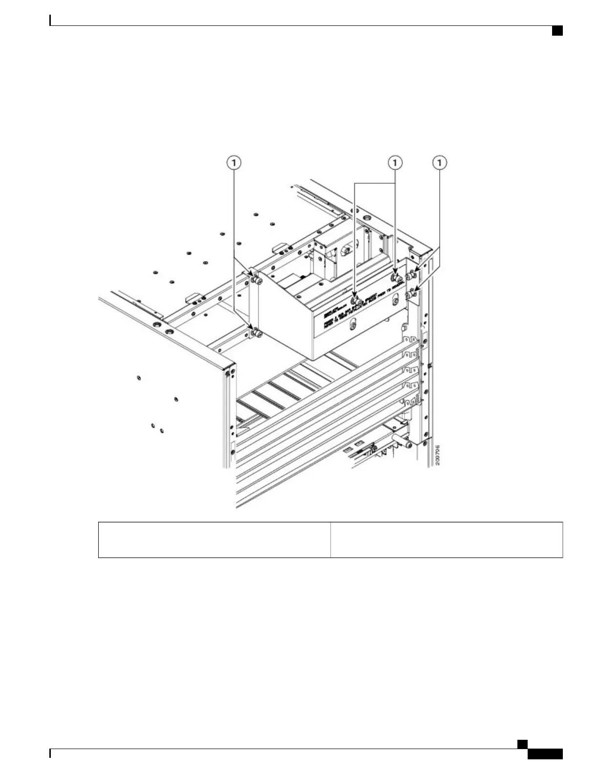
Figure 6: Removing the Power A Bus Bar Shipping Bracket
Captive screws securing Power A bus bar bracket to rear
of chassis
1
Step 2
Remove the Power A bus bar shipping bracket form the chassis and set it aside.
Step 3
Remove the Power A bus bar from the rear of the chassis. See Figure 7: Removing the Cover From the Power A Bus
Bar, on page 12.
The Power A bus bar is connected to the chassis with an internal cable. Be careful not to drop the power bus
bar.
Note
Cisco CRS Routers 16-Slot Line Card Chassis Enhanced Router Installation Guide
11
Installing Power Components
Installing the Power A Bus Bar

Other manuals for Cisco CRS Series

Questions and Answers:

Question and Answer IconNeed help?

Do you have a question about the Cisco CRS Series and is the answer not in the manual?

Cisco CRS Series Specifications

General IconGeneral
CategoryNetwork Router
Operating SystemCisco IOS XR
Form FactorModular chassis
Routing CapacityUp to 322 Tbps
Interface Support10 Gigabit Ethernet, 40 Gigabit Ethernet, 100 Gigabit Ethernet
Maximum ThroughputUp to 322 Tbps
Line Card Slots4, 8, 16
DimensionsVaries by chassis
WeightVaries by chassis
ModelCisco CRS Series

Related product manuals