EasyManuals Logo

Cisco CRS Series Installation Guide

Cisco CRS Series
54 pages
To Next Page IconTo Next Page
To Previous Page IconTo Previous Page
Page #12 background imageLoading...
Page #12 background image
Step 4
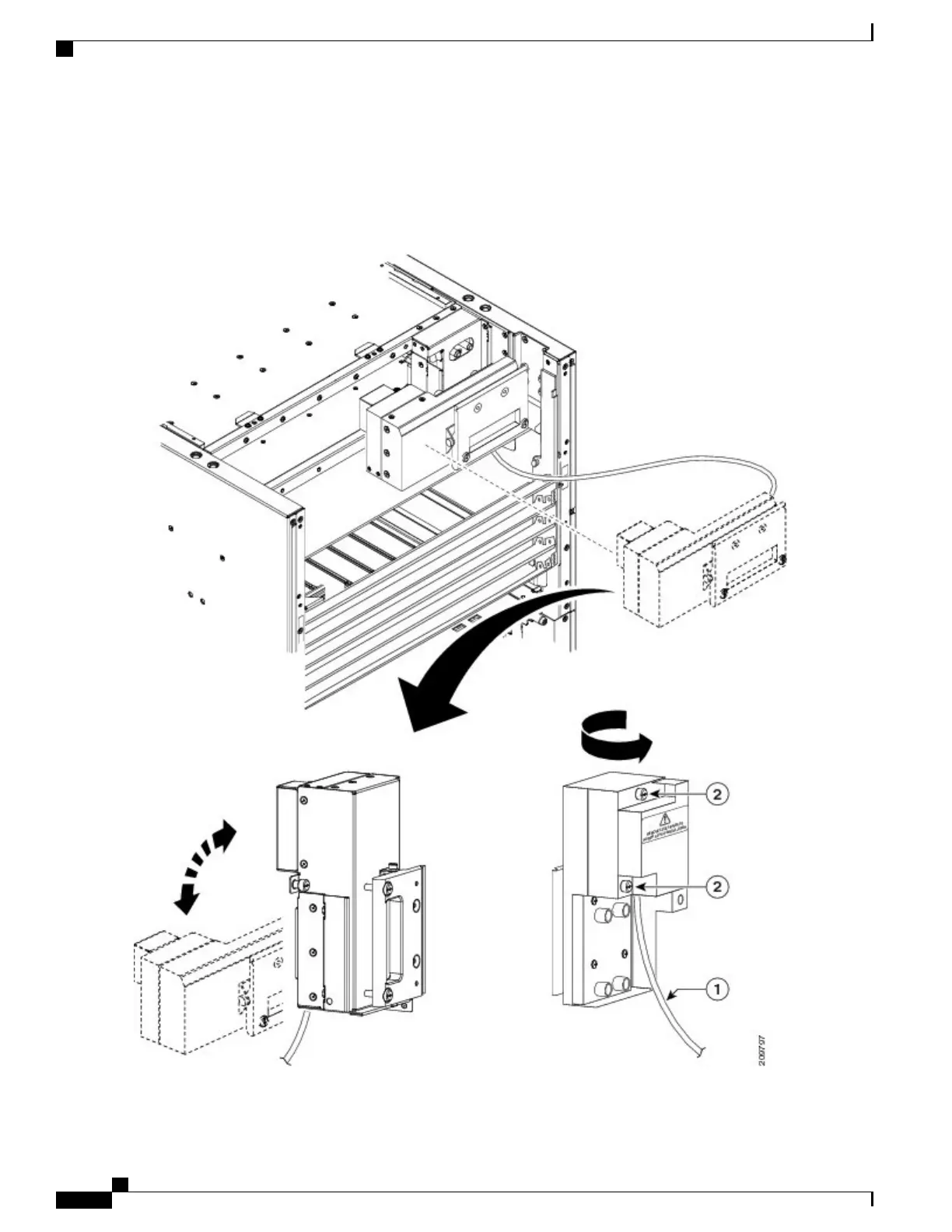
Remove the cover from the Power A bus bar by loosening the two captive screws that attach the cover to the bus bar.
See Figure 7: Removing the Cover From the Power A Bus Bar, on page 12.
Figure 7: Removing the Cover From the Power A Bus Bar
Cisco CRS Routers 16-Slot Line Card Chassis Enhanced Router Installation Guide
12
Installing Power Components
Installing the Power A Bus Bar

Other manuals for Cisco CRS Series

Questions and Answers:

Question and Answer IconNeed help?

Do you have a question about the Cisco CRS Series and is the answer not in the manual?

Cisco CRS Series Specifications

General IconGeneral
CategoryNetwork Router
Operating SystemCisco IOS XR
Form FactorModular chassis
Routing CapacityUp to 322 Tbps
Interface Support10 Gigabit Ethernet, 40 Gigabit Ethernet, 100 Gigabit Ethernet
Maximum ThroughputUp to 322 Tbps
Line Card Slots4, 8, 16
DimensionsVaries by chassis
WeightVaries by chassis
ModelCisco CRS Series

Related product manuals