Step 5
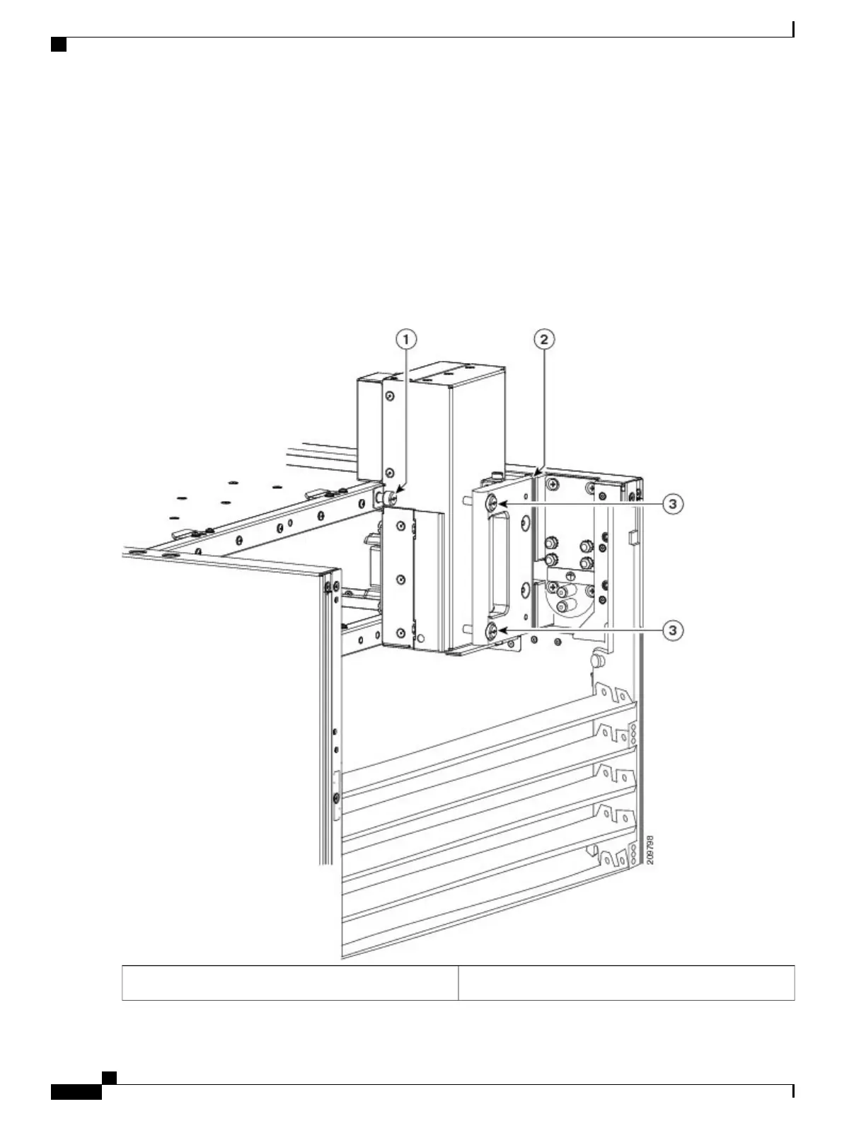
Position the power block vertically. Mate the power block pivot and chassis pivot point together. See item 2 in Figure
8: Power A Bus Bar Installed in Chassis, on page 14.
Step 6
Unscrew the two handle screws on the power bus bar and open the handle. See item 3 on Figure 8: Power A Bus Bar
Installed in Chassis, on page 14.
Step 7
Hold the power block cable to the side to keep clear of the power block connectors while seating the power block.
Step 8
Seat the power block and tighten the two screws on the handle. See item 3 in Figure 8: Power A Bus Bar Installed in
Chassis, on page 14.
Figure 8: Power A Bus Bar Installed in Chassis
Captive screw securing Power A bus bar to chassis1
Cisco CRS Routers 16-Slot Line Card Chassis Enhanced Router Installation Guide
14
Installing Power Components
Installing the Power A Bus Bar
 Loading...


