b) To decrease the door gap, loosen the five screws that secure the vertical trough to the chassis. Using the 2 mm hex
key wrench, tighten the bottom set screws (number 1 in the figure below) one full turn. Snug the five screws that
attach the vertical trough to the chassis and check the door alignment.
c) To increase the door gap, loosen the five screws that secure the vertical trough to the chassis. Using the 2 mm hex
key wrench, tighten the top set screws (number 2 in the figure below) one full turn. Snug the five screws that attach
the vertical trough to the chassis and check the door alignment.
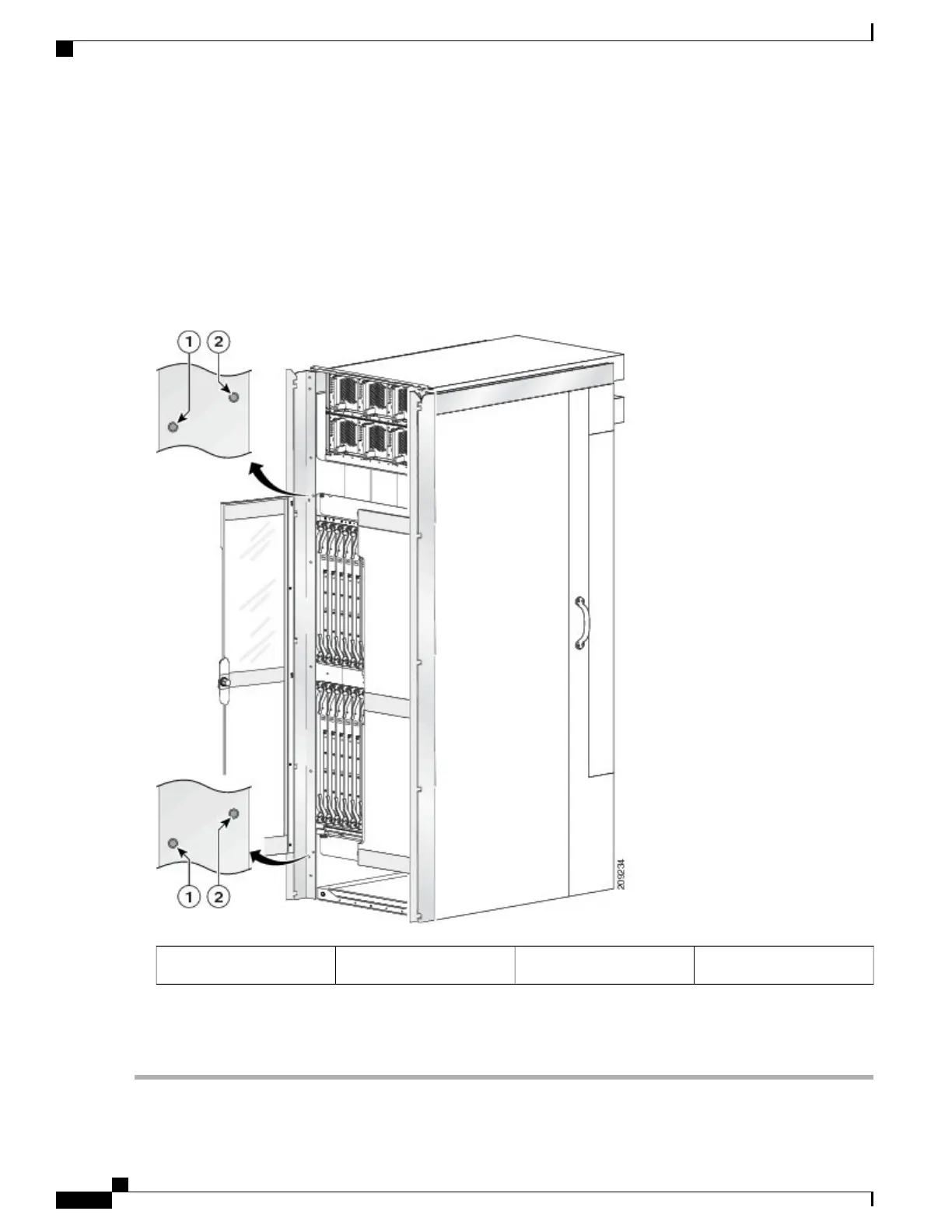
Figure 10: Aligning the Door on the Front of the Chassis - Left Door Shown
Top set screw2Bottom set screw1
d) Repeat the procedure as necessary until the doors are properly aligned.
e) Tighten the five screws that secure the vertical trough to the chassis.
Cisco CRS Carrier Routing System Fabric Card Chassis Installation Guide
14
Installing and Removing Exterior Cosmetic Components
Steps

 Loading...


