Step 9
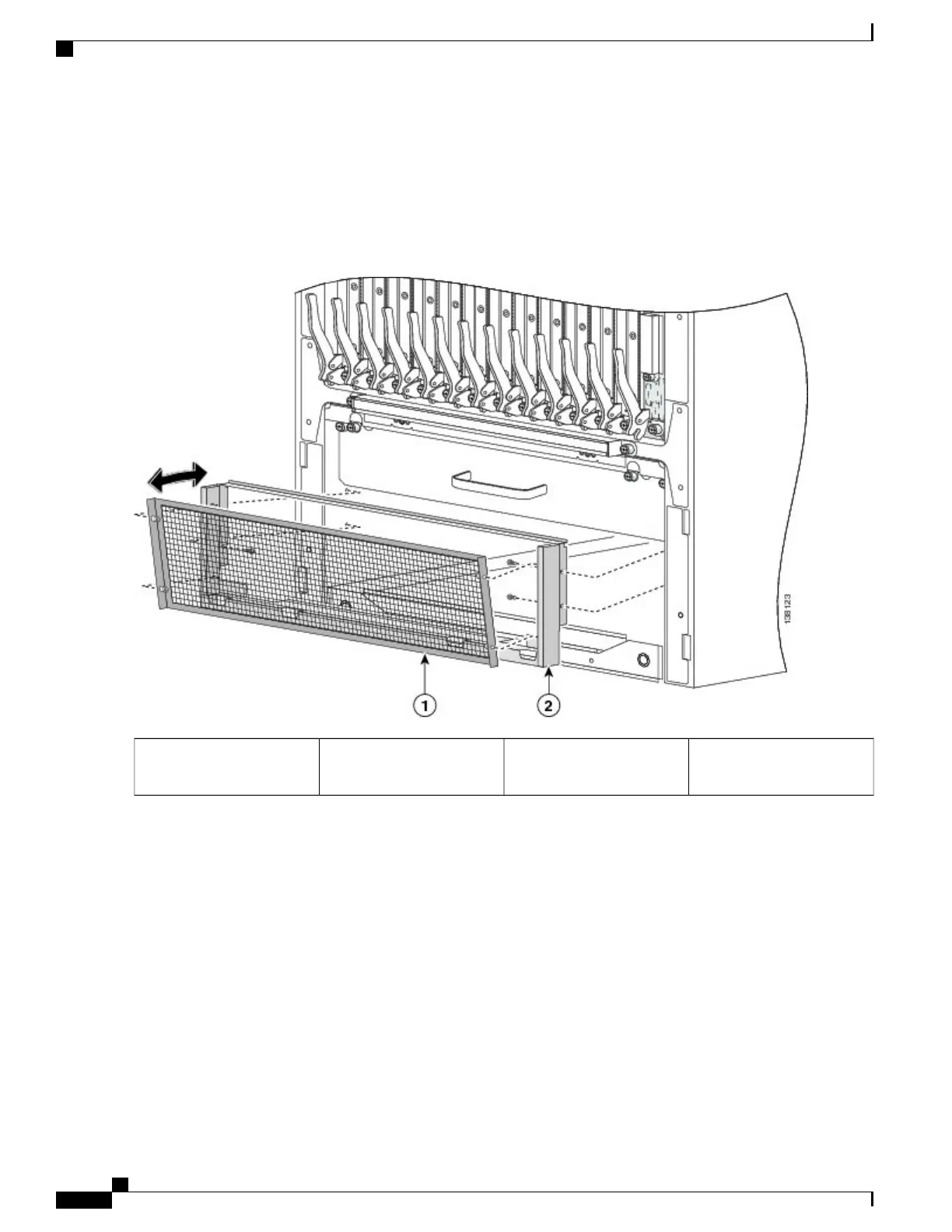
Use the screwdriver to loosen the four captive screws, two on each side, that attach the inlet grille screen to the frame
assembly. Remove the screen from the frame assembly. See the figure below.
Step 10
Remove the four screws, two on each side, that attach the frame assembly to the chassis. See the figure below.
Figure 15: Removing the Front (SFC) Side Inlet Screen and Lower Grille Frame Assembly
Lower grille screen frame
assembly
2Lower grille screen1
Cisco CRS Carrier Routing System Fabric Card Chassis Installation Guide
22
Installing and Removing Exterior Cosmetic Components
Steps

 Loading...


