EasyManuals Logo

Cisco CRS Manual

Cisco CRS
50 pages
To Next Page IconTo Next Page
To Previous Page IconTo Previous Page
Page #23 background imageLoading...
Page #23 background image
Step 11
Rotate the assembly forward, lift it away from the front (SFC) side of the chassis, and set it aside.
Step 12
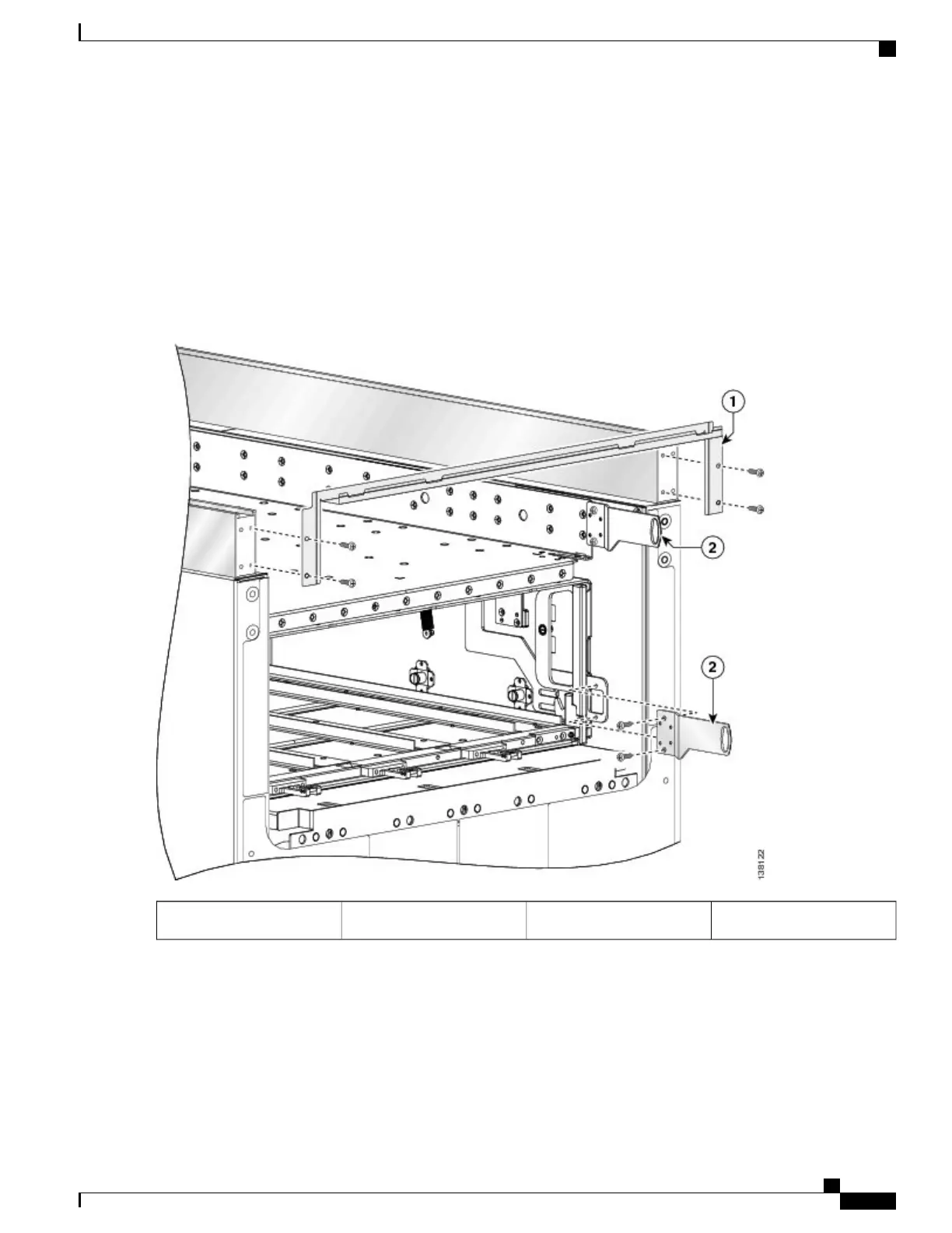
Remove the power shelf shutoff extenders (number 2 in the figure below) by unscrewing the four screws, two screws
per extender, and set the screws and the extenders aside.
Step 13
Remove the front upper grille support (number 1 in the figure below) from the unistruts by unscrewing the four M4x14-mm
flat head screws (two for each unistrut).
Step 14
Set the screws aside, then lift the grille support away from the front (SFC) side of the chassis, and set it aside.
Figure 16: Removing the Front (SFC) Side Upper Grille Support and Power Shutoff Extenders
Power shutoff extender2Front upper grille support1
Cisco CRS Carrier Routing System Fabric Card Chassis Installation Guide
23
Installing and Removing Exterior Cosmetic Components
Steps

Other manuals for Cisco CRS

Questions and Answers:

Question and Answer IconNeed help?

Do you have a question about the Cisco CRS and is the answer not in the manual?

Cisco CRS Specifications

General IconGeneral
Operating SystemCisco IOS XR
Product TypeCore Router
Form FactorModular Chassis
DimensionsVaries by chassis type
WeightVaries by chassis type
ArchitectureDistributed
Switch FabricMulti-stage
Interface SupportEthernet, SONET/SDH, OTN
Interfaces/PortsVaries by line card
Port DensityVaries by line card
Routing ProtocolBGP, IS-IS, OSPF, MPLS
ManagementCLI, SNMP
Power SupplyRedundant, hot-swappable
CoolingRedundant, Hot-swappable Fan Trays
Supported ProtocolsIPv4, IPv6, MPLS
Management InterfacesEthernet, console
Security FeaturesACLs

Related product manuals