Step 3
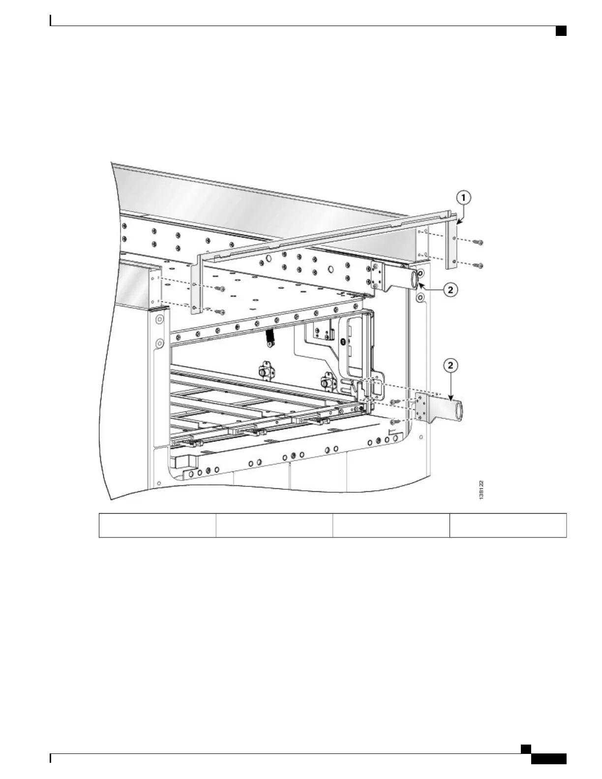
Attach the power shelf shutoff extenders (number 2 in the figure below) by inserting the four M4 panhead screws, two
for each power shelf shutoff extender, and tightening them with the screwdriver.
Figure 4: Attaching the Front (SFC) Side Upper Grille Support and Power Shelf Shutoff Extenders
Power shelf shutoff extender2Front upper grille support1
Step 4
Attach the front vertical cable troughs—one on the right and one on the left—to the front (SFC) side of the chassis (see
the figure below) by i nserting the 10 M4x14-mm flat head screws (5 on each side). Use the screwdriver to fasten screws
to attach the cable troughs firmly to the chassis.
Cisco CRS Carrier Routing System Fabric Card Chassis Installation Guide
7
Installing and Removing Exterior Cosmetic Components
Steps
 Loading...


